A urological catheter

A urinary catheter and urology technology, which is applied in the direction of balloon catheter, hypodermic injection equipment, pumping and pumping system, etc. It can solve the problems of fluid leakage, inconvenience for medical staff to check the condition, and removal of blood clots and necrotic tissue in patients, etc. problem, to achieve the effect of reducing friction

Inactive Publication Date: 2019-01-08
徐州百芈商贸有限公司
0 Cites 4 Cited by

AI-Extracted Technical Summary

Problems solved by technology

[0008] Aiming at the deficiencies of the prior art, the present invention provides a urological catheter, which solves the problem of leakage of urine, making it inconvenient for medica...

Abstract

A urological catheter includes a composite glass catheter. A lead end of that composite glass catheter body is provided with a catheter hole, the composite glass urethral catheter is provided with anair bag at a groove of the composite glass urethral catheter, the tail end of the composite glass catheter is fixedly connected with a voiding tube, A second valve is arranged on one end of the urination tube close to the composite glass urination tube, and a first valve is fixedly connected on the other end of the urination tube close to the urination bag, the urination bag is marked with a graduation, a drainage tube is arranged on the right lower end of the urination bag, and a drainage plug is arranged on the other end of the drainage tube. A manual inflator, an air bag, a syringe, a firstvalve and a second valve are arrange to solve that problems of liquid leakage and urine leakage, inconvenience for medical personnel to check the condition and inconvenience for patient to remove blood clots and necrotic tissues existing in urine and urine through a catheter.

Application Domain

Balloon catheterMedical devices +2

Technology Topic

Remove bloodUrine +12

Image

  • A urological catheter
  • A urological catheter
  • A urological catheter

Examples

  • Experimental program(1)

Example Embodiment

[0024] The technical solutions in the embodiments of the present invention will be clearly and completely described below in conjunction with the accompanying drawings in the embodiments of the present invention. Obviously, the described embodiments are only a part of the embodiments of the present invention, rather than all the embodiments. Based on the embodiments of the present invention, all other embodiments obtained by those of ordinary skill in the art without creative work shall fall within the protection scope of the present invention.
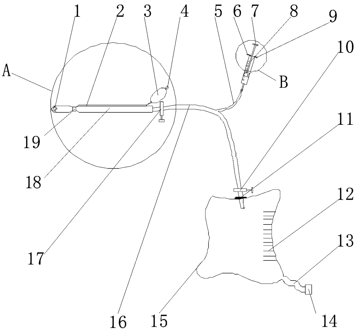
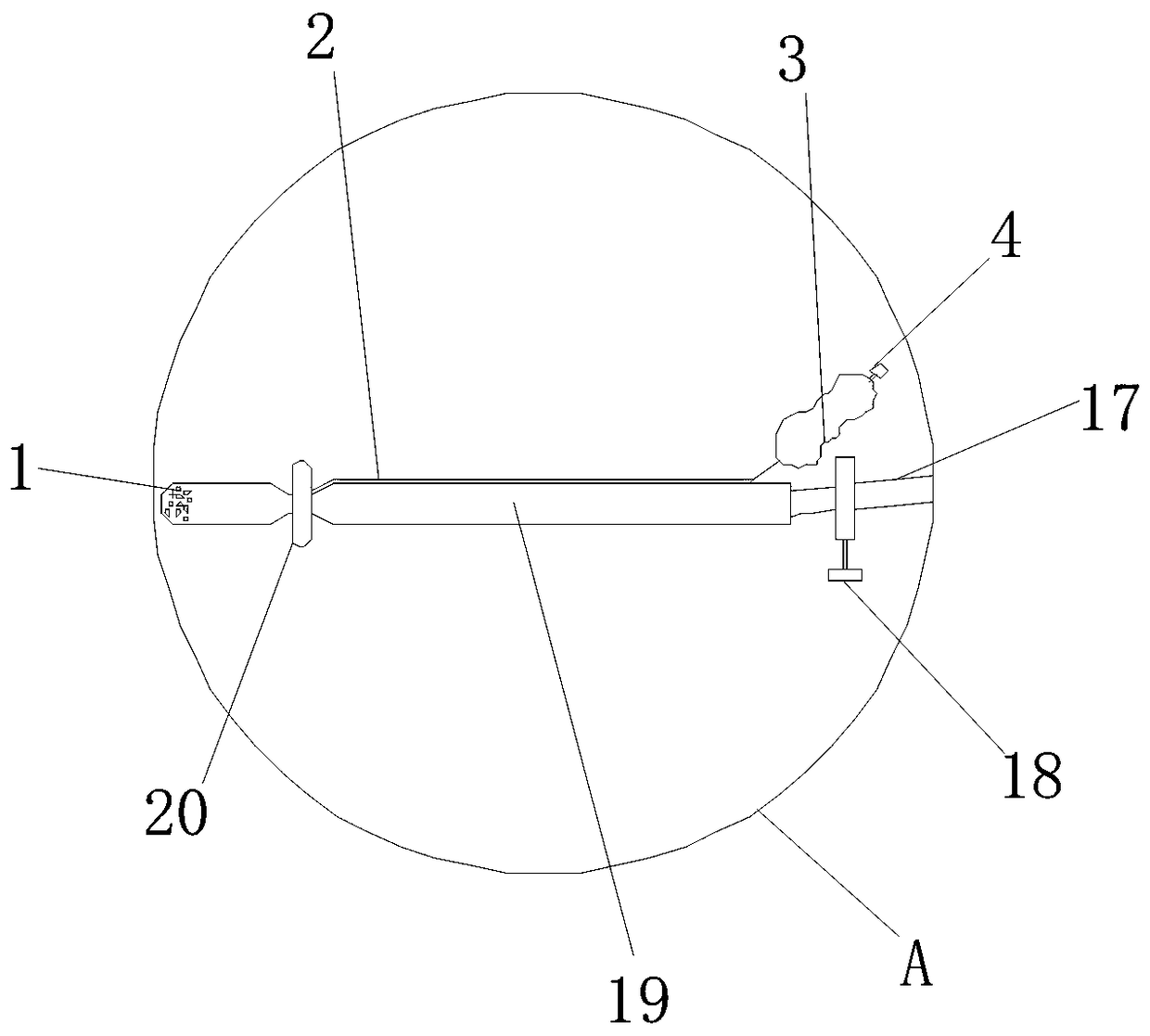
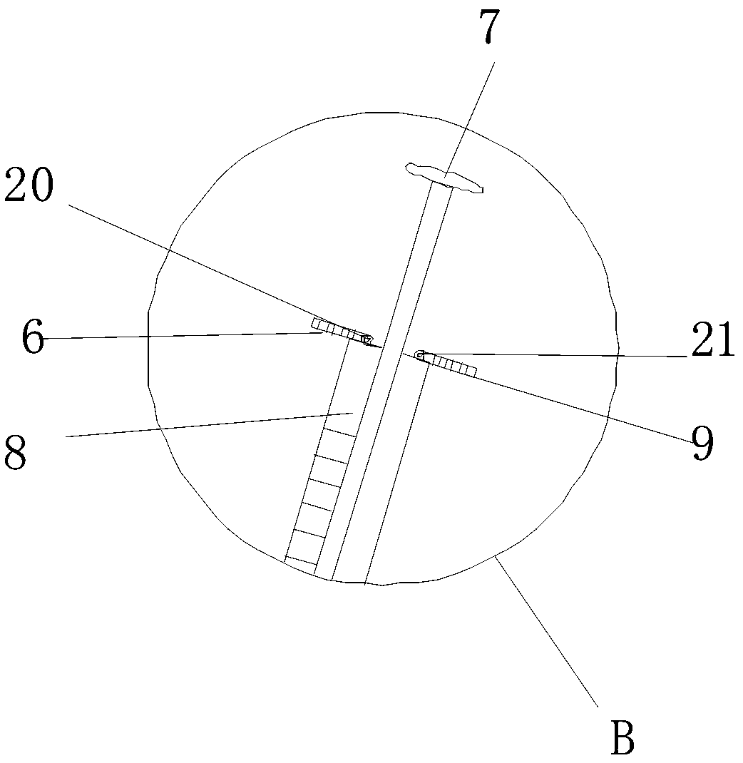
[0025] Such as Figure 1-4 As shown, the present invention provides a technical solution: a urinary catheter includes a composite glass catheter 18, the front end of the composite glass catheter 18 is provided with a catheter hole 1, and the composite glass catheter 18 The groove of the glass urinary catheter 18 is provided with an airbag 19 to wrap the composite glass urinary catheter 18, and the airbag 19 is connected to the manual inflator 3 through the air inlet pipe 2, and the end of the manual inflator 3 is provided with a unidirectional Plug 4, use the manual inflator 3 to inflate the airbag 3 through the intake pipe 2 to inflate it to a certain degree. The one-way plug 4 can prevent the gas in the airbag from leaking, and will not leak during use. Naturally deflate. Pull out the one-way plug 4 after use to deflate the airbag 3, which solves the problem of leakage of urine due to the gap between the catheter and the bladder muscle due to the absence of a fixed catheter. The middle part of the tube 16 is provided with a hose 5, one end of the hose 5 is interference-connected with a syringe 8, and the bottom end of the syringe 8 is fixedly connected with a base 7, and both sides of the syringe 8 below the base 7 are respectively The first movable shaft 20 and the second movable shaft 21 are fixedly connected, the first movable shaft 20 is fixedly connected with a first pressure telescopic rod 6, and the second movable shaft 21 is fixedly connected with a second pressure movable shaft 9, Close the first valve 10 and the second valve 17, pull the base 7 on the syringe 8 to evacuate the air in the urinary tube 16, and stretch to a certain extent. The first movable shaft 20 and the second movable shaft 21 extend the first pressure rod 6 and the second pressure telescopic rod 9 are pressed against the base 7 to fix its working state, and a low pressure is formed in the urination tube 16, which can well discharge the patient's urine and urine containing a little clot and necrotic tissue. The first pressure The telescopic rod 6 and the second pressure telescopic rod 9 have a certain pressure inside, and they will not easily retract when they are stretched. The second valve 17 is provided on the end of the urinary tube 16 near the composite glass catheter 18, so The other end of the urination tube (16) is fixedly connected to the urine storage bag 15 with a first valve 10, and a sealing rubber ring 11 is provided at the junction of the urine storage bag 15 and the urination tube 16 below the first valve 10. The urine storage bag 15 is marked with a scale 12, the lower right end of the urine storage bag 15 is provided with an excretion tube 13 and the other end of the excretion tube 13 is provided with a drain plug 14.
[0026] Before use, close the first valve 10 and the second valve 17, pull the base 7 on the syringe 8 to evacuate the air in the urinary tube 16 and stretch it to a certain extent to pass through the first movable shaft 20 and the second movable shaft 21. A pressure telescopic rod 6 and a second pressure telescopic rod 9 are pressed against the base 7 to fix their working state, and a low pressure is formed in the urination tube 16, which can well discharge the patient's urine and urine containing some clots and necrotic tissue , The first pressure telescopic rod 6 and the second pressure telescopic rod 9 have a certain pressure inside, they will not easily retract when they are stretched, and then insert the composite glass catheter 18 into the patient's body. At this time, use manual inflation The device 3 inflates the airbag 3 through the air intake pipe 2 to make it expand to a certain extent. The one-way plug 4 can prevent the air in the airbag from leaking, and will not naturally deflate when it is used. Pull out the one-way plug 4 to deflate the airbag 3, and then open the first valve 10 and the second valve 17, the urine can enter the composite glass catheter 18 into the urinary tube 16 through the catheter hole 1. Then enter the urine storage bag 15, which is made of transparent plastic material, which is convenient for medical staff to check. Finally, the urine can be discharged through the excretion tube 13 by opening the excretion plug 14.
[0027] In summary, the present invention provides manual inflator 3, air bag 19, syringe 8, first valve 10, second valve 17, urine bag 15, first pressure telescopic rod 6, second pressure telescopic rod 9, and base 7 Solve the problem of leakage of fluid and urine, inconvenience for medical staff to check the condition, and inability to help the patient to remove some clots and necrotic tissue in urine and urine through the catheter.
[0028] It should be noted that in this article, relational terms such as first and second are only used to distinguish one entity or operation from another entity or operation, and do not necessarily require or imply one of these entities or operations. There is any such actual relationship or order between. Moreover, the terms "include", "include" or any other variants thereof are intended to cover non-exclusive inclusion, so that a process, method, article or device including a series of elements not only includes those elements, but also includes those that are not explicitly listed Other elements of, or also include elements inherent to this process, method, article or equipment.
[0029] Although the embodiments of the present invention have been shown and described, those of ordinary skill in the art can understand that various changes, modifications, and substitutions can be made to these embodiments without departing from the principle and spirit of the present invention. And variations, the scope of the present invention is defined by the appended claims and their equivalents.

PUM

no PUM

Description & Claims & Application Information

We can also present the details of the Description, Claims and Application information to help users get a comprehensive understanding of the technical details of the patent, such as background art, summary of invention, brief description of drawings, description of embodiments, and other original content. On the other hand, users can also determine the specific scope of protection of the technology through the list of claims; as well as understand the changes in the life cycle of the technology with the presentation of the patent timeline. Login to view more.

Similar technology patents

Diverter valve

InactiveUS20070199599A1lower torquereduce friction
Owner:AMERIKAM

Static pressure workbench for forming gear grinding machine

Owner:浙江嘉力宝传动设备有限公司

Classification and recommendation of technical efficacy words

  • reduce friction

Hand force feedback and sensing system

InactiveUS7138976B1reduce friction
Owner:RUTGERS UNIVERSITY

Electrical connector with voltage detection point insulation shield

ActiveUS6843685B1reduce frictionreduces wear and clean
Owner:THOMAS & BETTS INT INC

One piece low drag septum

ActiveUS20070093778A1reduce friction
Owner:BECTON DICKINSON & CO

Combination oil ring

InactiveUS20060113730A1reduce frictionenhanced capability
Owner:TOYOTA JIDOSHA KK +1

Apparatus for deploying endoscope

InactiveUS20100198012A1reduce frictionless effective
Owner:SCOPEGUARD LTD
Why Eureka
Try Eureka