Large-surface spraying flexible cable robot

A surface spraying and robot technology, applied in the direction of manipulators, spraying devices, manufacturing tools, etc., can solve the problems that the working range cannot fully meet the requirements, the working range of wall-climbing robots is small, and the safety performance is low, so as to achieve easy operation and high spraying efficiency , the effect of a large working range

Pending Publication Date: 2019-01-08
YUNNAN KUNMING SHIPBUILDING DESIGN & RESEARCH INSTITUTE
0 Cites 5 Cited by

AI-Extracted Technical Summary

Problems solved by technology

However, my country's aerial work vehicle products still cannot fully meet the requirements in terms of operating height and working range.
There are also a small number of shipyards that use wall-climbing robots for on-site painting operation...

Abstract

The invention relates to a large-surface spraying flexible cable robot, and is used for performing high-efficiency paint spraying on large surfaces of ships, large airplanes and the like. The flexiblecable robot comprises a spraying device, the spraying device is driven by flexible cables to move freely, the spraying device is located between the flexible cables and move between the flexible cables, and the free moving track of the spraying device can cover and spray the large surfaces. The flexible cable robot can be effectively applied to perform high-efficiency paint spraying on the largesurfaces of the ships, the large airplanes and the like, the effective working range is wide, and the spraying efficiency is high.

Application Domain

Technology Topic

Image

  • Large-surface spraying flexible cable robot
  • Large-surface spraying flexible cable robot
  • Large-surface spraying flexible cable robot

Examples

  • Experimental program(1)

Example Embodiment

[0023] The present invention will be further described below in conjunction with the accompanying drawings and embodiments.
[0024] The definition of the present invention faces the appended figure 1 When the left side is the left side, the attached figure 1 When the back is right.
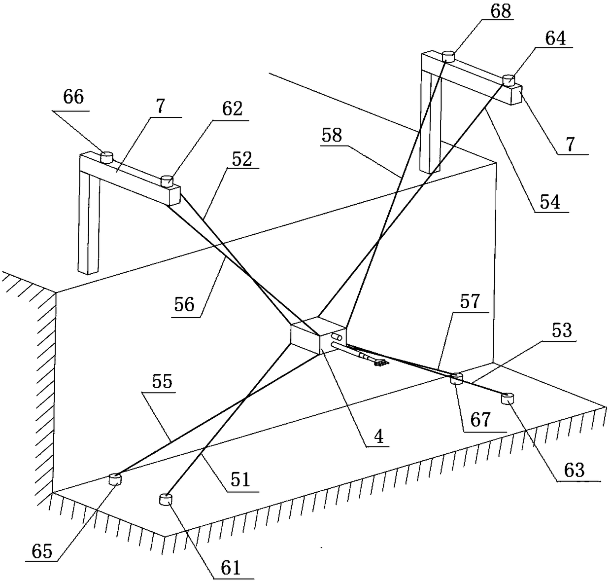
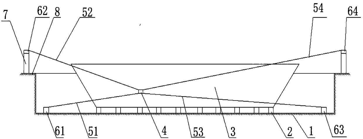
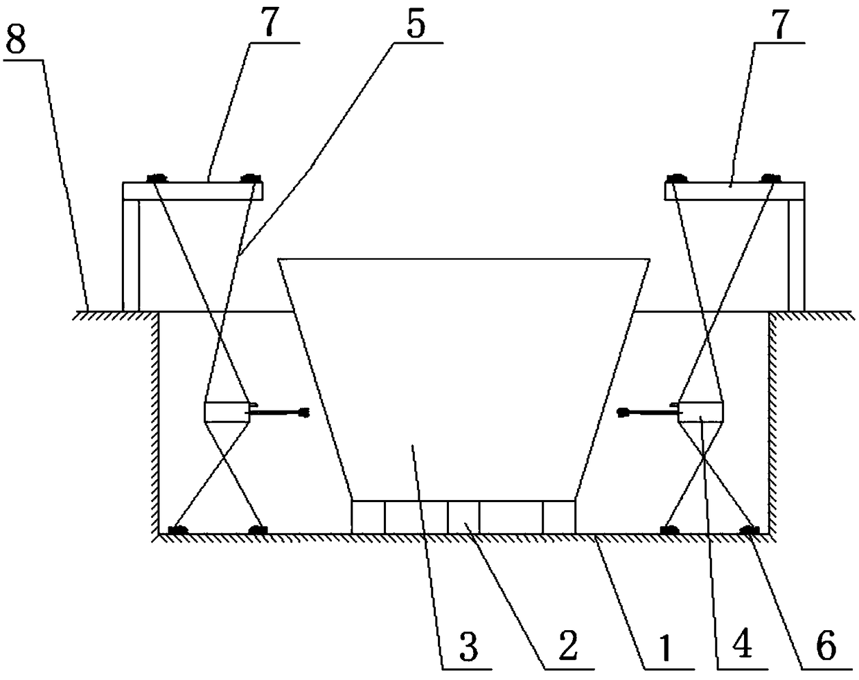
[0025] like Figure 1 to Figure 4 As shown, the large-surface spraying cable robot of the present invention is used for surface spraying of ships. The ship 3 is placed on the keel pier 2. The keel pier 2 and the ship 3 are located at the lower part 1 of the dry dock as a whole, and the top surface of the ship 3 is higher than the top of the dry dock. 8.
[0026] Wherein a large surface of ship 3 is provided with spraying device 4, and this spraying device 4 comprises distance measuring device 41, spray pipe 42 and spray gun 43, and described distance measuring device 41 and spray pipe 42 are arranged on the same side of spraying device 4, described A spray gun 43 is arranged at the end of the spray pipe 42 and drives the spray gun 43 to move. The distance measuring device 41 is used to measure the surface distance between the spraying device 4 and the ship 3. The spray pipe 42 is a telescopic spray pipe that can drive the spray gun 43 to expand and contract back and forth, and the spray gun 43 is a spray gun with an adjustable spray angle. The spray gun 43 Adjust the spraying angle according to the curved shape of the ship's surface, and spray the ship's surface.
[0027]The spraying device 4 is connected with a cable 5, and is driven by the cable 5 to move freely. In order to make the spraying device 4 adjustable in the direction of six degrees of freedom and ensure that the working area of ​​the spraying device 4 covers the entire large surface, eight vertices of the spraying device 4 provided by the present invention are respectively connected to the first cable 51 and the second cable. 52. One end of the third flexible cable 53, the fourth flexible cable 54, the fifth flexible cable 55, the sixth flexible cable 56, the seventh flexible cable 57 and the eighth flexible cable 58 passes through the first flexible cable 51, the second flexible cable The extension and recovery of flexible wire 52, the third flexible wire 53, the fourth flexible wire 54, the fifth flexible wire 55, the sixth flexible wire 56, the seventh flexible wire 57 and the eighth flexible wire 58, the spraying device 4 is driven Attached to the first flexible cable 51, the second flexible cable 52, the third flexible cable 53, the fourth flexible cable 54, the fifth flexible cable 55, the sixth flexible cable 56, the seventh flexible cable 57 and the eighth flexible cable 58 to move between.
[0028] Correspondingly, a cable driving device 6 is provided to control the extension or recovery of the cable 5 . Cable driving device 6 comprises a first driving device 61, a second driving device 62, a third driving device 63, a fourth driving device 64, a fifth driving device 65, a sixth driving device 66, a seventh driving device 67 and an eighth driving device. The driving device 68 drives and connects the first flexible cable 51, the second flexible cable 52, the third flexible cable 53, the fourth flexible cable 54, the fifth flexible cable 55, the sixth flexible cable 56, the seventh flexible cable 57 and the first flexible cable respectively. The other end corresponding to the eight flexible cables 58.
[0029] Usually, four flexible cable driving devices 6 are fixedly installed on the lower part 1 of the dry dock, and the flexible cable driving devices 6 form a group of two and are respectively located on the left and right sides of the lower part 1 of the dry dock. The cable driving devices 6 are respectively a first driving device 61 , a third driving device 63 , a fifth driving device 65 and a seventh driving device 67 . Wherein, the first driving device 61 is arranged near the fifth driving device 65, and both are located on the same level; the third driving device 63 is arranged near the seventh driving device 67, and both are located on the same level.
[0030] Frames 7 are fixedly installed on the left and right sides of the top 8 of the dry dock, and two cable driving devices 6 are respectively arranged on each frame 7, which are respectively the second driving device 62, the fourth driving device 64, and the sixth driving device. The driving device 66 and the eighth driving device 68 . Wherein, the second driving device 62 is arranged near the sixth driving device 66, and both are jointly fixed on one of the frame 7; the fourth driving device 64 is arranged near the eighth driving device 68, and both are jointly fixed. On the corresponding other rack 7.
[0031] In order to facilitate the control of the spraying device 4, the first flexible cable 51 and the fifth flexible cable 55 are intersected; the second flexible cable 52 is intersected with the sixth flexible cable 56; the third flexible cable 53 and the seventh flexible cable 57 Between the cross setting; between the fourth flexible cable 54 and the eighth flexible cable 58 cross setting.
[0032] Under the control of the control system, the flexible cable driving device 6 realizes the extension or recovery of the flexible cable 5, thereby driving the spraying device 4 to move freely in the space of the entire ship spraying outer surface area, and keeping the spray gun 43 at a certain distance from the ship surface .
[0033] Wherein, the flexible cable 5 may be made of flexible materials such as steel, plastic, or hemp rope.
[0034] When using the large surface spraying cable robot of the present invention to carry out ship surface spraying, such as image 3 As shown, the present embodiment respectively arranges a set of cable robots on two sides of the ship 3 . First, the spraying device 4 is driven to move on the surface of the ship. At this time, the distance measuring device 41 moves along the horizontal direction to obtain the position information of the hull surface of one layer, and then moves down for a certain distance, and then the distance measuring device 41 is moved in the opposite direction along the horizontal direction. A new layer of position information of the hull surface is obtained, and the position information of the entire hull surface to be sprayed can be obtained by scanning the position information of the hull surface line by line.
[0035] Then, continue to manipulate the flexible cable 5 to drive the spraying device 4 to repeat the previous track. At this time, the spray gun 43 sprayed the surface of the ship. When the flexible cable 5 moved to the limit position and the spray gun 43 could not directly spray, the spray pipe 42 stretched and drove The spray gun 43 moves forward to the desired spraying position, and then the spray gun 43 adjusts the spraying angle according to the shape of the curved surface of the hull to spray the surface of the hull.
[0036] In the area where the flexible cable 5 interferes with the hull, use the flexible cable robot to drive the spraying device 4 to move to the vicinity of the position of the surface to be sprayed, where the spraying device 4 does not interfere with the hull, and then the telescopic spray pipe 42 drives the spray gun 43 to Stretch out before, close to the position that needs spraying, spray gun 43 is automatically adjusted to the optimum spraying angle and sprays on the hull surface.
[0037] The above embodiments are only used to illustrate the technical solutions of the present invention, rather than to limit them; although the present invention has been described in detail with reference to the foregoing embodiments, those of ordinary skill in the art can still understand the foregoing embodiments. Modifications are made to the technical solutions described, or equivalent replacements are made to some of the technical features; and these modifications or replacements do not make the essence of the corresponding technical solutions deviate from the spirit and scope of the technical solutions claimed in the present invention.

PUM

no PUM

Description & Claims & Application Information

We can also present the details of the Description, Claims and Application information to help users get a comprehensive understanding of the technical details of the patent, such as background art, summary of invention, brief description of drawings, description of embodiments, and other original content. On the other hand, users can also determine the specific scope of protection of the technology through the list of claims; as well as understand the changes in the life cycle of the technology with the presentation of the patent timeline. Login to view more.

Similar technology patents

Classification and recommendation of technical efficacy words

  • Easy to install
  • Simple structural design

Ultrasound guidance system

InactiveUS20070073155A1Easy to installAccurate and simple needle placementUltrasonic/sonic/infrasonic diagnosticsSurgical needlesUltrasound guidanceNeedle guidance
Owner:ULTRASOUND VENTURES

A graphic OSD controller integrated into video processing chip

InactiveCN101150682AReduce storage space requirementsSimple structural designTelevision system detailsColor television detailsWork patternBitmap
Owner:XI AN JIAOTONG UNIV
Why Eureka
Try Eureka