Production device for casting castings and avoiding generating cavities in castings

A production device and casting technology, applied in the field of casting casting, can solve the problems of mold dislocation, fast cooling speed, slow cooling time of raw materials, etc., and achieve the effect of accurate mold installation position, convenient installation and disassembly, and good finished product effect

Inactive Publication Date: 2019-01-08
陈李杰
2 Cites 2 Cited by

AI-Extracted Technical Summary

Problems solved by technology

[0003] 1. If the positioning setting is not set, it is easy to cause the mold to be dislocated, thereby reducing the accuracy of the mold installation position;
[0004] 2. For example, the patent application number is CN201610326020.7 for a metal casting casting mold. The first template and the second template are connected in the slot, and the fixation is not firm enough. Although the installation and disassembly are relatively simple, the raw materials are easy to overflow and affect the quality of the finished product. ;
[0005] 3. For example, the...

Method used

As shown in Fig. 1 and Fig. 6, the first bump 3 is evenly distributed on the second mold 4, and the second mold 4 forms a dismounting structure on the first mold 2 by the first bump 3, the first bump 3 It plays the role of positioning and increases the accuracy of the connection position between the second mold 4 and the first mold 2. As shown in Figure 1, the closest distance between the lower outside of the third mold 6 and the second mold 4 is equal to the bottom of the third mold 6 The closest distance between the outside and the first mold 2, and the third mold 6 is connected to the grooves of the first mold 2 and the second mold 4 through the second bump 5, so that the finished product is relatively uniform, and the second bump 5 can Position the third mold 6 to increase the accuracy of the connection position between the third mold 6 and the first mold 2 and the second mold 4;
As shown in Fig. 7, the first cooling device 15 includes a first heat pipe 1501, a first spring 1502, a first heat conduction block 1503 and a rubber block 1504, and the left side of...

Abstract

The invention discloses a production device for casting castings and avoiding generating cavities in the castings. The production device comprises a table frame and a third mold, wherein a first moldis pasted onto a right side of the middle of an upper surface of the table frame; a first bump is fixedly connected to the right side of a second mold; a lower surface of the third mold is closely glued to the second mold and the first mold; a first bolt is connected to the third mold in a penetrating manner; a feed opening is formed in a left side above the third mold; a water tank is reserved ata center position below the third mold; a second heat dissipation device is arranged on the right side above a heating rod; and the second heat dissipation device comprises a second heat conducting pipe, a second heat conducting block and a rubber handle connecting block. The production device for casting castings and avoiding generating cavities in the castings can conveniently process tubular castings, has relatively accurate mold mounting positions, can conveniently take out finished products, can avoid generating bubbles and cavities in the finished products, and can be cooled rapidly.

Application Domain

Foundry mouldsFoundry cores +1

Technology Topic

EngineeringWater tanks +2

Image

  • Production device for casting castings and avoiding generating cavities in castings
  • Production device for casting castings and avoiding generating cavities in castings
  • Production device for casting castings and avoiding generating cavities in castings

Examples

  • Experimental program(1)

Example Embodiment

[0037] The technical solutions in the embodiments of the present invention will be clearly and completely described below with reference to the accompanying drawings in the embodiments of the present invention. Obviously, the described embodiments are only a part of the embodiments of the present invention, but not all of the embodiments. Based on the embodiments of the present invention, all other embodiments obtained by those of ordinary skill in the art without creative efforts shall fall within the protection scope of the present invention.
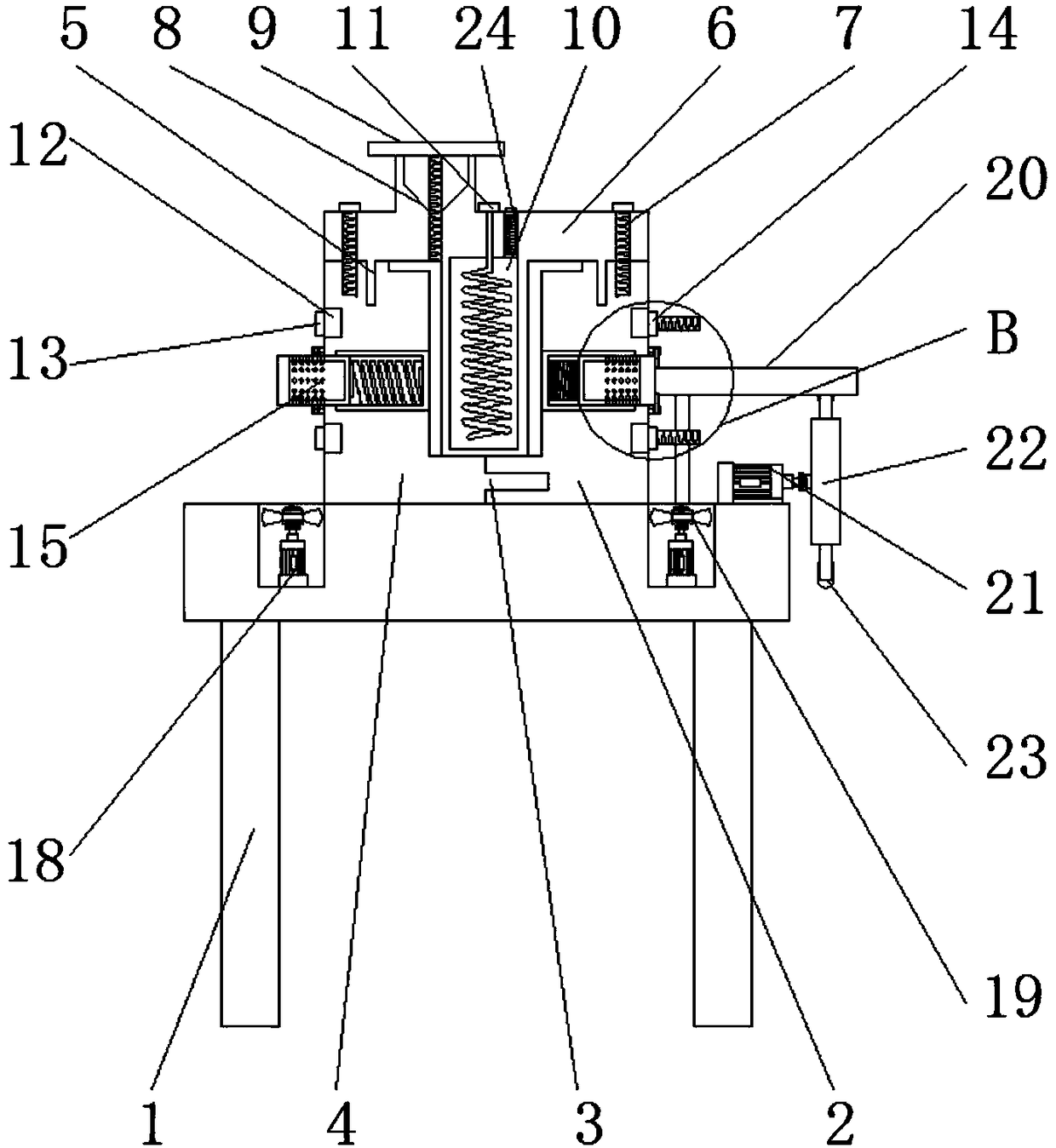
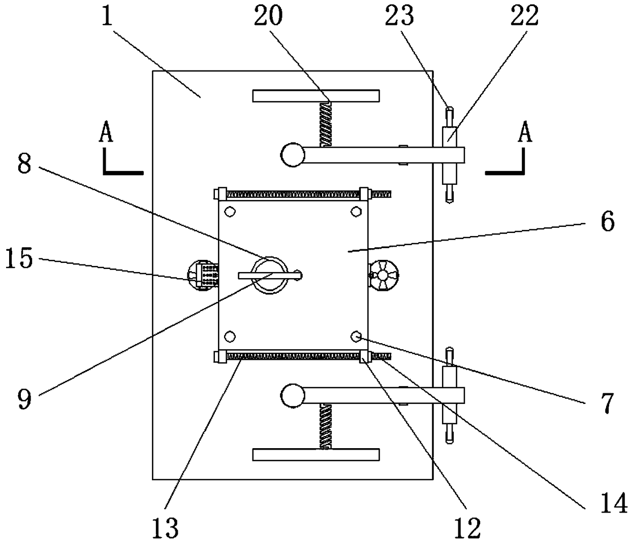
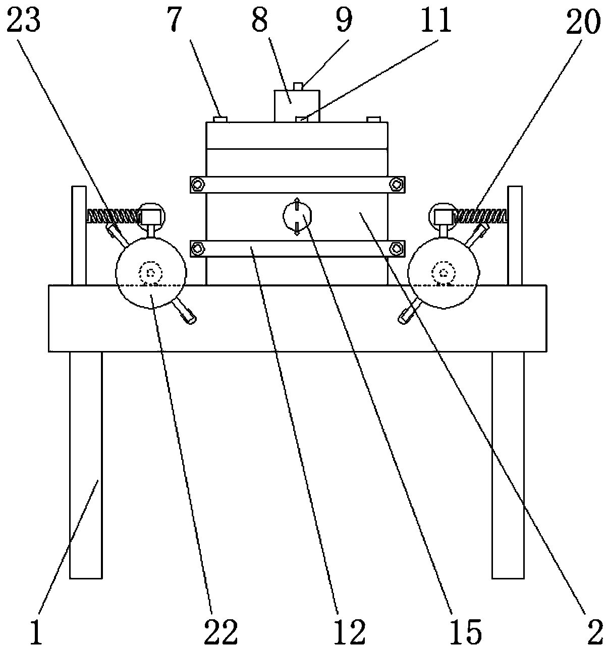
[0038] see Figure 1-9, the present invention provides a technical solution: a production device for casting castings that prevents cavities from being generated in castings, including a table frame 1, a first mold 2, a first bump 3, a second mold 4, a second bump 5, The third mold 6, the first bolt 7, the feeding port 8, the first connecting rod 9, the water tank 10, the heating rod 11, the first connecting plate 12, the second bolt 13, the nut 14, the first cooling device 15, the first Two connecting rods 16, fixed plate 17, first motor 18, fan 19, exhaust device 20, second motor 21, connection plate 22, rubber rod 23, second heat sink 24, the upper surface middle part right side of table frame 1 The first mold 2 is pasted and connected, and the left side of the first mold 2 is connected with the second mold 4, and the right side of the second mold 4 is fixedly connected with the first bump 3, and the first bump 3 is connected through the second mold. a left side of mold 2;
[0039] The lower surface of the third mold 6 is in close contact with the second mold 4 and the first mold 2, and the bottom of the third mold 6 is fixedly connected with the second bump 5, and the second bump 5 is connected between the second mold 4 and the first mold 2. The first mold 2 is connected through, the third mold 6 is connected with the first bolt 7, and the bottom of the first bolt 7 is screwed with the second mold 4 and the first mold 2, and the top left of the third mold 6 A blanking port 8 is opened on the side, and the inside of the blanking port 8 is connected with a first connecting rod 9, and a water tank 10 is reserved at the lower center of the third mold 6, and a heating rod 11 is arranged inside the water tank 10, and the heating The rod 11 is connected through the third mold 6, and the upper right side of the heating rod 11 is provided with a second heat sink 24, and the second heat sink 24 is connected through the third mold 6, and the second heat sink 24 includes a second heat conduction The pipe 2401, the second heat conduction block 2402 and the rubber handle connection block 2403, and the second heat conduction pipe 2401 is connected with the second heat conduction block 2402 by the internal thread, and the rubber handle connection block 2403 is pasted and connected on the top of the second heat conduction block 2402, and the rubber The handle connection block 2403 runs through and connects above the third mold 6;
[0040] The upper and lower sides on the left side of the second mold 4 and the upper and lower sides on the right side of the first mold 2 are connected with the first connecting plate 12 through the groove, and the second bolt 13 is connected through the first connecting plate 12, and the second bolt 13 A nut 14 is threadedly connected to the right side of the second mold 4, a first cooling device 15 is connected through the left middle part of the second mold 4 and the right middle part of the first mold 2, and the upper and lower sides of the first cooling device 15 are provided with The second connecting rod 16, the second connecting rod 16 is fixedly connected with the right side of the first mold 2 and the left side of the second mold 4, and the second connecting rod 16 is rotatably connected with a fixed plate 17;
[0041] A first motor 18 is fixedly connected to the top of the table frame 1, and a fan 19 is fixedly connected to the top of the first motor 18, and the fan 19 is provided on the right side of the first mold 2 and the left side of the second mold 4, The front and rear sides of the second mold 4 are all provided with an exhaust device 20, and the bottom of the exhaust device 20 is fixedly connected on the upper surface of the table frame 1, and the exhaust device 20 includes a second connecting plate 2001, a second spring 2002, The third connecting plate 2003, the rubber hammer 2004 and the third connecting rod 2005, and the right side of the second connecting plate 2001 is connected with the third connecting plate 2003 through the second spring 2002, and the rear side of the third connecting plate 2003 is fixedly connected with a rubber Hammer 2004, and the lower part of the third connecting plate 2003 is nested and connected to the third connecting rod 2005, the lower right side of the exhaust device 20 is provided with a second motor 21, and the lower part of the second motor 21 is fixedly connected to the table frame 1, the right side of the second motor 21 is fixedly connected with a connection plate 22, and a rubber rod 23 is fixedly connected with the connection plate 22.
[0042] like figure 1 and Image 6 Among them, the first bumps 3 are evenly distributed on the second mold 4, and the second mold 4 forms a disassembly structure on the first mold 2 through the first bumps 3, and the first bumps 3 play a positioning role, increasing the second The accuracy of the connection position of the second mold 4 and the first mold 2, such as figure 1 The minimum distance between the outside of the third mold 6 and the second mold 4 is equal to the minimum distance between the outside of the third mold 6 and the first mold 2, and the third mold 6 is connected to the first mold through the second bump 5. 2 and the second mold 4 are connected by slots, so that the finished product is relatively uniform, and the third mold 6 can be positioned through the second bump 5, increasing the accuracy of the connection position between the third mold 6 and the first mold 2 and the second mold 4 sex;
[0043] like figure 1 The longitudinal section shape of the first connecting rod 9 is "T" shape, and the first connecting rod 9 is connected with the feeding port 8 by threaded connection, so the position of the first connecting rod 9 can be controlled to ensure the first connection. When the top of the rod 9 is in contact with the upper surface of the blanking port 8, the lower surface of the first connecting rod 9 is parallel to the upper surface of the second mold 4, thereby ensuring the smoothness of the upper surface of the finished product; figure 1 The bottom of the middle heating rod 11 has a spiral structure, and the distance between the four sides of the bottom of the heating rod 11 and the inner wall of the water tank 10 is equal, so that the water in the water tank 10 is heated evenly, thereby achieving the effect of uniform heating for the raw materials;
[0044] like Figure 7 The first heat dissipation device 15 includes a first heat pipe 1501, a first spring 1502, a first heat conduction block 1503 and a rubber block 1504. The left side of the inner wall of the first heat pipe 1501 is fixedly connected with a first The heat conduction block 1503, the right side of the first heat conduction block 1503 is pasted with a rubber block 1504, such as Figure 7 The first heat conduction block 1503 forms a telescopic structure on the first heat conduction tube 1501, and the right outer side of the first heat conduction block 1503 has a porous structure, so the heat can be dissipated rapidly through the holes on the first heat conduction block 1503, and the first spring 1502 The elastic effect of the first heat conduction block 1503 can be easily moved out of the device, so as to achieve the purpose of heat dissipation;
[0045] like figure 1 and figure 2 Among them, two first heat sinks 15 and two first motors 18 are arranged symmetrically with respect to the vertical central axis of the third mold 6, and the vertical central axis of the first heat sink 15 and the vertical central axis of the first motor 18 are located at On the same vertical plane, the fan 19 can specifically increase the air circulation velocity around the first heat dissipation device 15, thereby achieving the purpose of rapid heat dissipation;
[0046] like Figure 4 and Figure 8 The third connecting plate 2003 forms a rotating structure on the third connecting rod 2005, and the third connecting plate 2003 forms a telescopic structure on the second connecting plate 2001. The rotation of the third connecting plate 2003 can drive the rubber hammer 2004 to hit the first A mold 2 and a second mold 4, and the rubber hammer 2004 can swing back and forth through the elastic action of the second spring 2002, thereby achieving the effect of discharging the gas in the raw material through impact, such as Figure 4 and Figure 8 The middle rubber rod 23 forms a rotating structure on the table frame 1 through the connecting plate 22, and the distance between the side of the rubber rod 23 away from the connecting plate 22 and the connecting plate 22 is greater than the distance between the bottom of the third connecting plate 2003 and the connecting plate 22 size, the rotation of the third connecting plate 2003 can be powered by the rubber rod 23 .
[0047] Working principle: When using the casting production device for preventing cavities in castings, first connect the second mold 4 with the groove of the first mold 2 through the first bump 3, and the first bump 3 acts to connect the second The role of the positioning of the mold 4 makes the connection position between the first bump 3 and the first mold 2 more accurate, and then the first connecting plate 12 is respectively connected with the second mold 4 and the slot of the first bump 3, and then the second bolt 13 successively pass through the first connecting plates 12 on the left and right sides and then threadedly connect with the nut 14. Turning the nut 14 clockwise can reduce the gap between the two first connecting plates 12, so that the second mold 4 and the first connecting plate 12 can be connected One mold 2 is firmly fixed, and then the third mold 6 is connected with the second mold 4 and the first mold 2 through the second bump 5, and then the first bolt 7 is inserted through the third mold 6 and the first mold 2 and the first mold 2. The first bump 3 is threaded to fix the third mold 6, thereby completing the assembly work of the mold;
[0048] Then the heating rod 11 is switched on to heat the water in the water tank 10, and then the raw material is poured into the first mold 2 and the first bump 3 through the discharge port 8, and the heat in the water tank 10 will pass through the third mold 6 to Raw material transmission can increase the fluidity of raw materials, and ensure that the gaps in the first mold 2, the second mold 4, and the third mold 6 can be filled, and after filling, the power supply of the second motor 21 whose model is Y90S-2 When the switch is turned on, the second motor 21 will drive the rubber rod 23 to rotate through the connecting plate 22. When the rubber rod 23 rotates and contacts the third connecting plate 2003, it will push the third connecting plate 2003 to rotate on the third connecting rod 2005, so that The rubber hammer 2004 bumps into the first mold 2 and the second mold 4, and when the rubber rod 23 leaves the surface of the third connecting plate 2003, the rubber hammer 2004 will move toward the second connecting plate 2001 due to the elasticity of the second spring 2002. Return to the original position, through the rotation of the rubber rod 23, the rubber hammer 2004 can be driven to continuously hit the first mold 2 and the second mold 4, and the air in the raw material can be discharged through the discharge port 8 after being hit;
[0049] After the exhaust is completed, the second motor 21 and the heating rod 11 are turned off, and then the first connecting rod 9 is rotated so that the top of the first connecting rod 9 is in contact with the upper surface of the feeding port 8, and the feeding port 8 Closed to prevent the device from vibrating due to the operation process during the cooling process, thereby sticking to the feeding port 8, causing the blocking of the feeding port 8 or causing the finished product to be uneven here, and then the fixing plate 17 is connected to the second connection. After the rod 16 rotates 90° and leaves the surface of the first heat sink 15, the first heat conduction block 1503 will move outward due to the elastic action of the first spring 1502, and the heat in the raw material will be transferred to the first heat conduction block through the first heat conduction pipe 1501 1503, through the first heat conduction block 1503, then turn on the power switch of the first motor 18 of model Y90S-2, and the first motor 18 drives the fan 19 to rotate, thereby driving the air circulation around the first heat conduction block 1503, And the first heat conduction block 1503 has a porous structure, so the heat dissipation speed is faster. At the same time, the rotation of the rubber handle connection block 2403 drives the second heat conduction block 2402 to turn out of the third mold 6, and the heat in the water tank 10 will pass through the second heat conduction block. The tube 2401 is transferred to the second heat conduction block 2402 and discharged outwards, so as to increase the cooling speed, and the right side of the first heat conduction block 1503 and the top of the second heat conduction block 2402 are respectively provided with rubber blocks 1504 and rubber handles to connect Block 2403, when the rubber block 1504 is in contact with the first mold 2 or the second mold 4, the heat cannot be dissipated outwards and does not affect the pouring process. When the rubber handle connection block 2403 contacts the third mold 6, the heat in the water tank 10 also cannot be distributed;
[0050] After cooling and solidifying, unscrew the nut 14 from the second bolt 13 and extract it from the first connecting plate 12, then turn the first bolt 7 counterclockwise to take it off from the third mold 6, and then the third mold 6 1. When the first mold 2 and the second mold 4 are separated, the finished product can be easily taken out, which is the whole process of using the production device for castings to prevent cavities from being produced in the castings.
[0051] Although the embodiments of the present invention have been shown and described, those skilled in the art can understand that various changes, modifications and substitutions can be made to these embodiments without departing from the principle and spirit of the present invention. and modifications, the scope of the invention is defined by the appended claims and their equivalents.

PUM

no PUM

Description & Claims & Application Information

We can also present the details of the Description, Claims and Application information to help users get a comprehensive understanding of the technical details of the patent, such as background art, summary of invention, brief description of drawings, description of embodiments, and other original content. On the other hand, users can also determine the specific scope of protection of the technology through the list of claims; as well as understand the changes in the life cycle of the technology with the presentation of the patent timeline. Login to view more.

Similar technology patents

Supersonic ejector

ActiveCN104847708AThe airflow is well mixedeasy to process
Owner:CHINA ACAD OF AEROSPACE AERODYNAMICS

Flexible pile cap for composite foundation

Owner:XIAN UNIV OF SCI & TECH

Low-RCS ultra-wideband metamaterial wave absorber with insensitive polarization and capable of transmitting visible light

ActiveCN111430926AOvercome the complex structure of absorbing materialsEasy to process
Owner:HARBIN INST OF TECH

Classification and recommendation of technical efficacy words

  • Easy to process

Crease type crash energy absorption box

ActiveCN101638076ALow Load Uniformity FactorEasy to process
Owner:王博 +1

Bionic impeller for exhaust hood

ActiveCN104100570AEasy to processReduce leading edge pressure shock
Owner:HANGZHOU DE&E ELECTRICAL CO LTD
Why Eureka
Try Eureka