Quantitative bidirectional powder spreading device and laser selective melting forming device thereof

A powder spreading device and powder spreading technology are applied in the fields of laser selective melting and forming device and quantitative two-way powder spreading device, which can solve the problems of increasing the movement stroke of the powder spreading arm, increasing the size of the forming equipment, reducing the stroke, etc., so as to shorten the atmosphere. The effect of preparation time, shortened forming time, and reduced motion stroke

Inactive Publication Date: 2019-01-08
XI AN JIAOTONG UNIV
View PDF6 Cites 4 Cited by
  • Summary
  • Abstract
  • Description
  • Claims
  • Application Information

AI Technical Summary

Problems solved by technology

[0003] At present, for the SLM forming process, the powder spreading structure is mostly in the form of powder feeding from the bottom. A powder feeding cylinder is placed next to the forming cylinder, and the powder feeding cylinder rises to a certain height to provide a certain amount of metal powder for scraper powder spreading. This method increases the The size of the forming equipment increases the volume of the equipment, the space utilization rate is low, and the movement stroke of the powder spreading arm is increased. For the powder feeding structure under the SLM forming, 30%-50% of the total time for the part is used for the powder spreading process. The forming equipment For one-way powder feeding, it takes a long time for the powder spreading mechanism to drive the scraper to reciprocate. When the size of the forming equipment is small, the time taken for powder spreading increases significantly. Therefore, the design of the powder spreading structure with a reduced stroke and fewer reciprocating times of the scraper will reduce the total forming consumption. important when

Method used


Image

  • Quantitative bidirectional powder spreading device and laser selective melting forming device thereof
  • Quantitative bidirectional powder spreading device and laser selective melting forming device thereof
  • Quantitative bidirectional powder spreading device and laser selective melting forming device thereof

Examples


Embodiment Construction

[0029] The technical solution of the present invention will be further described below in conjunction with the accompanying drawings and specific embodiments.

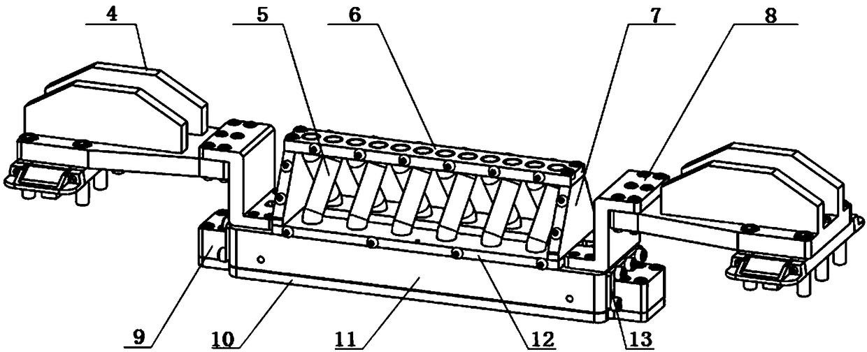
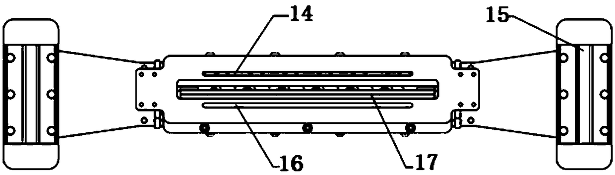
[0030] The invention provides a quantitative two-way powder spreading device, which comprises a powder spreading structure and a powder falling structure; the powder falling structure is arranged above the powder spreading structure.

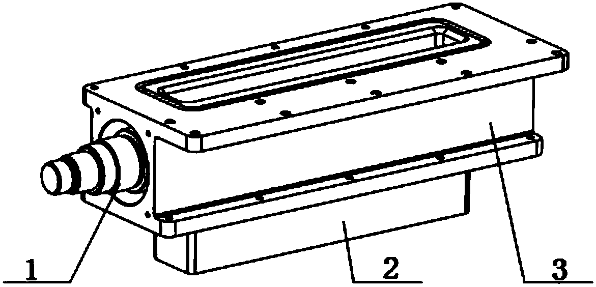
[0031] Such as image 3 As shown, the powder falling structure includes a powder falling chamber 3, and a powder falling shaft 1 is arranged in the powder falling chamber 3, and the powder falling shaft 1 can rotate in the powder falling chamber 3; specifically, the upper and lower parts of the powder falling chamber 3 are both An opening is provided, the upper opening is used to load powder, and the lower opening is used to drop powder to the powder spreading structure.

[0032] Preferably, the opening directly below the lower part of the powder falling chamber 3 is opposite to the ent...


PUM

PropertyMeasurementUnit
diameteraaaaaaaaaa

Abstract

The invention discloses a quantitative bidirectional powder spreading device and a laser selective melting forming device thereof. A powder dropping structure and a powder spreading structure are included. The powder dropping structure comprises a powder dropping tank. An opening for dropping powder is formed in the lower portion of the powder dropping tank. A rotatable powder dropping shaft is arranged in the powder dropping tank. The powder spreading device comprises a powder dropping plate. A plurality of distribution guide pipes are arranged on the upper portion of the powder dropping plate and communicate with an inner cavity of the powder dropping plate. Scraper brackets are connected to the two ends of the powder dropping plate. Motion sliders are arranged under the scraper bracketsand move on preset rails. A scraper is arranged on the bottom face of the powder dropping plate. The two sides of the scraper are each provided with a powder dropping groove, the powder dropping grooves are openings in the bottom face of the powder dropping plate. With the adoption of the upper powder dropping mode, a powder feeding structure is arranged on the upper portion of the equipment to replace a lower powder feeding mode, the inner size of a forming cavity is reduced substantially, the stroke of a powder spreading arm is reduced, and forming time is shortened.

Description

technical field [0001] The invention belongs to the technical field of laser selective melting and forming, specifically relates to a quantitative two-way powder spreading device, and also relates to a laser selective melting and forming device. Background technique [0002] Selective laser melting technology (SLM) is an advanced laser additive manufacturing technology developed based on the basic principle of prototype manufacturing technology. It is a common additive method for metal net shaping. Most of the forming materials are titanium alloy, aluminum alloy and stainless steel, etc. According to the characteristics of SLM forming process, metal powder with a particle size of about 10-53 μm needs to be evenly spread on the forming substrate. According to different forming materials and optical path systems, each layer The thickness is about 30 μm. In the SLM forming process, in addition to laser power, scanning speed, filling strategy, forming atmosphere, etc., the thic...

Claims


Application Information

Patent Timeline
Patent Type & Authority Applications(China)
IPC IPC(8): B22F3/105B33Y30/00
CPCB33Y30/00B22F10/00B22F12/57B22F10/28B22F12/67B22F12/55B22F12/50B22F12/226Y02P10/25
Inventor 魏正英向羽张树哲李俊峰杨理想姜立昊
Owner XI AN JIAOTONG UNIV
Why Eureka
Try Eureka