A lawn crawling robot with autonomous obstacle avoidance function
A crawling robot and grassland technology, which is applied in the direction of instruments, motor vehicles, two-dimensional position/channel control, etc., can solve the problems of low wheel grip, lack of autonomous obstacle avoidance, lack of shock absorption, etc., and achieve climbing powerful effect
- Summary
- Abstract
- Description
- Claims
- Application Information
AI Technical Summary
Problems solved by technology
Method used
Image

Examples
specific Embodiment approach 1
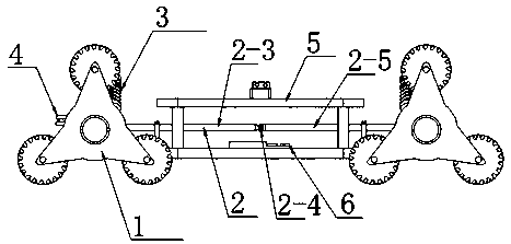
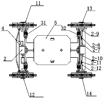
[0010] Specific implementation mode one: combine Figure 1-Figure 3 Describe this embodiment, a grass crawling robot with autonomous obstacle avoidance function described in this embodiment includes a wheel 1, a transmission system 2, a shock absorption system 3, a steering system 4, a fuselage 5 and a control system 6, the wheel Part 1 includes left front wheel 12, right front wheel 11, left rear wheel 14 and right rear wheel 13, transmission system 2 includes stepper motor 2-1, reducer I2-2, drive shaft I2-3, universal joint Device I2-4, transmission shaft II2-5, reducer II2-6, transmission shaft III2-7, universal coupling II2-8, transmission shaft IV2-9, transmission shaft V2-10, universal coupling III2 -11 and power transmission shaft VI2-12, damping system 3 comprises front wheel damping system 31 and rear wheel damping system 32, and steering system 4 comprises steering gear 43, steering gear rod 42 and connecting rod 41, and control system 6 is based on main The main c...
specific Embodiment approach 2
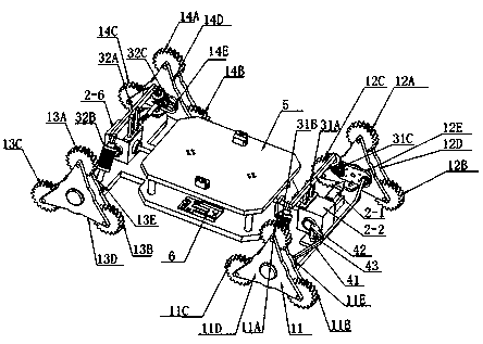
[0020] Specific implementation mode two: combination Figure 1-Figure 3 Describe this embodiment, the wheel part 1 of this embodiment includes the left front wheel 12, the right front wheel 11, the left rear wheel 14 and the right rear wheel 13, and the left front wheel 12 includes the left front wheel I12A, the left front wheel II12B , the left front wheel III12C, the left front triangular wheel train support frame 12D and the left front L-shaped support 12E, wherein the left front wheel I12A, the left front wheel II12B and the left front wheel III12C are fixed at the end of the left front triangular wheel train support frame 12D by pin shafts, the left front The triangular gear train support frame 12D is fixedly connected with the left front L-shaped support 12E, and the left front L-shaped support 12E is fixedly connected with the fuselage 5;
[0021] The right front wheel 11 includes a right front wheel I11A, a right front wheel II11B, a right front wheel III11C, a right f...
specific Embodiment approach 3
[0024] Specific implementation mode three: combination Figure 1-Figure 3 Describe this embodiment, the transmission system 2 described in this embodiment includes a stepping motor 2-1, a speed reducer I2-2, a transmission shaft I2-3, a universal joint I2-4, a transmission shaft II2-5, a speed reducer II2-6, transmission shaft III2-7, universal coupling II2-8, transmission shaft IV2-9, transmission shaft V2-10, universal coupling III2-11 and transmission shaft VI2-12, stepper motor 2 -1 is fixedly connected with the reducer I2-2, the reducer I2-2 is fixedly connected with the drive shaft I2-3, the drive shaft I2-3 is fixedly connected with the drive shaft II2-5 through the universal coupling I2-4, and the drive shaft II2-5 is fixedly connected to reducer II2-6, reducer II2-6 is fixedly connected to drive shaft III2-7, drive shaft III2-7 is fixedly connected to drive shaft IV2-9 through universal coupling II2-8, and the transmission The shaft IV2-9 passes through the right rea...
PUM
 Abstract
Description
Claims
Application Information
 - R&D
- Intellectual Property
- Life Sciences
- Materials
- Tech Scout
- Unparalleled Data Quality
- Higher Quality Content
- 60% Fewer Hallucinations
Browse by: Latest US Patents, China's latest patents, Technical Efficacy Thesaurus, Application Domain, Technology Topic, Popular Technical Reports.
© 2025 PatSnap. All rights reserved.Legal|Privacy policy|Modern Slavery Act Transparency Statement|Sitemap|About US| Contact US: help@patsnap.com