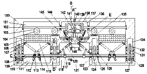
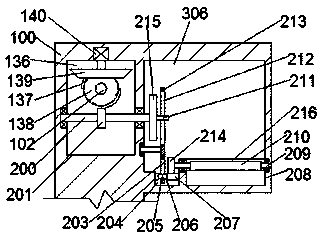
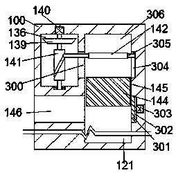
[0023] Combine below Figure 1-6 The present invention will be described in detail.
[0024] Reference Figure 1-6 According to an embodiment of the present invention, an automatic paper folding machine includes a box body 100 in which a rotating cavity 136 is fixed, and a rotating motor 140 is fixed on the upper end wall of the rotating cavity 136. The output shaft of 140 is rotatably connected with the lower end wall of the rotating cavity 136, the outer surface of the output shaft of the rotating motor 140 is fixedly provided with a driving bevel gear 139 and a roller 141, and the front wall of the rotating cavity 136 is connected with a communicating cavity penetrating forward and backward. 300, the left and right end walls of the communication cavity 300 are provided with sliding posts 305 that are slidably connected to the outer surface of the drum 141. The front wall of the communication cavity 300 is connected with an opening 306, and the front wall of the opening 306 is fixed A front sliding cavity 304 with an opening facing the opening 306, the sliding post 305 is connected with the left and right end walls of the front sliding cavity 304 in sliding fit, and the outer surface of the sliding post 305 is fixedly provided with a pressure plate located in the opening 306 142. Connecting rods 102 are symmetrically provided on the left and right end walls of the rotating cavity 136 to rotate. The left and right end walls of the rotating cavity 136 are symmetrically provided with paper feeding chambers 101 with downward openings. The connecting rods 102 and the paper feeding The cavity 101 is rotatably connected to the end wall of the rotating cavity 136. The rear end wall of the paper feeding cavity 101 is provided with a symmetrical rod. The outer surface of the rod is fixed with a conveying wheel 103 and the connecting rod 102. The meshing worm gear 104, the lower end surface of the paper feeding cavity 101 is fixedly provided with a friction strip 135, the conveying wheel 103 near the rotating cavity 136 is attached to the friction strip 135, and the outer surface of the connecting rod 102 is fixed There are a driven bevel gear 138 in the rotating cavity 136 that is engaged with the driving bevel gear 139 and a main gear 137 in the rotating cavity 136. The connecting column 200 rotates through the rotating cavity 136. The outer surface of the rotating cavity 136 is fixedly provided with a helical gear 201 located in the rotating cavity 136 and meshing with the main gear 137. The front wall of the rotating cavity 136 is provided with an open cavity 306, the outer surface of the connecting post 200 is fixedly provided with a transmission gear 215 located in the open cavity 306, and the front end of the transmission gear 215 is fixedly provided with a sliding rod 211 away from the center position, and The back end wall of the cavity 306 is rotatably provided with a swing plate 213. The swing plate 213 is fixedly provided with an upper groove 212 and a lower groove 203 penetrating forward and backward, and the sliding rod 211 is connected with the upper groove 212 in a sliding fit. The lower end wall of the open cavity 306 is connected with a through cavity 204, and a power rack 207 is provided in a sliding fit connection with the front and rear ends of the through cavity 204. The power rack 207 is fixedly provided with a connecting cavity 206 that penetrates up and down. The front and rear walls of the connecting cavity 206 are fixedly provided with a connecting block 205 that is slidably fitted with the lower groove 203, the front wall of the through cavity 204 is provided with an upper cavity 216 with an opening facing upward, and the lower end wall of the upper cavity 216 is connected with The pendulum cavity 208 with the opening facing the rotating cavity 136 is rotated with the front end wall of the upper cavity 216 to provide a movable The power rod 209 rotatably penetrates the upper cavity 216, and the outer surface of the power rod 209 is fixedly provided with a swing rod 210 located in the upper cavity 216 and in contact with the lower end wall of the upper cavity 216 and A passive gear 214 located in the open cavity 306 and meshed with the upper end surface of the power rack 207, the pendulum cavity 208 is connected to the center end wall of the rotating cavity 136 and communicates with the rotating cavity 136 and penetrates up and down The penetrating cavity 145 is provided with pressure blocks 144 slidingly on the left and right end walls of the penetrating cavity 145.
[0025] Beneficially or illustratively, the lower end wall of the penetrating cavity 145 is connected with an open cavity 121, and a connection that penetrates back and forth and communicates with the external space is fixed between the penetrating cavity 145 and the rear end wall of the open cavity 121. Cavity 146, between the penetrating cavity 145 opposite to the connecting cavity 146 and the front end wall of the opening cavity 121 is fixedly provided with a pushing cavity 302 opening towards the opening cavity 121, and the front end wall of the pushing cavity 302 is fixed There is an air cylinder 303, the push rod of the air cylinder 303 is fixedly provided with a push plate 301, the left and right end walls of the opening cavity 121 are rotatably provided with a symmetrical rotating rod 116, and the rotating rod 116 is fixedly provided with a sliding groove 120 penetrating forward and backward. , The fixed point fixed on the front end of the pressure block 144 is connected with the sliding groove 120 in a sliding fit, the left and right end walls of the open cavity 121 are fixed with guide posts 119, and the left and right end walls of the open cavity 121 have long The rod 108 is threadedly matched with the long rod 108 and provided with a threaded block 117 that is symmetrical and slide-fitted with the guide post 119. A connecting rod 118 is provided to rotate between the threaded block 117 and the rotating rod 116. The left and right end walls of the open cavity 121 are provided with symmetrical sliding cavities 110 communicating with the paper feeding cavity 101, and the sliding cavity 110 is provided with a cavity 134 on the end wall away from the open cavity 121.
[0026] Beneficially or exemplarily, a side cavity 123 is provided close to the end wall of the open cavity 121, and a rotating motor 124 is fixedly installed in the side cavity 123 close to the end wall of the open cavity 121. The output shaft of the rotating motor 124 is connected to the The end walls of the side cavity 123 are rotatably connected, the outer surface of the output shaft of the rotary motor 124 is fixedly provided with a driving gear 126, the left and right end walls of the side cavity 123 are rotatably provided with a rotating column 122, and the outer surface of the rotating column 122 is fixed There is a driven gear 125 engaged with the driving gear 126, an inner cavity 402 is fixed in the rotating column 122, the long rod 108 penetrates the inner cavity 402, and the outer surface of the long rod 108 is fixed The top cavity 401 is located in the connecting rod 102 and has symmetrical openings facing the inner cavity 402. The left and right end walls of the top cavity 401 are slidably provided with top rods 400 extending into the inner cavity 402. The long rod 108 rotatably penetrates the sliding cavity 110 and is connected to the cavity 134 away from the end wall of the opening cavity 121 in rotation and fit, and the outer surface of the long rod 108 is fixedly provided with a power gear 129 located in the cavity 134, The upper side of the power gear 129 is provided with an interlocking gear 131 that is rotatably connected with the left and right end walls of the cavity 134, and the interlocking gear 131 is provided with a tooth slidingly engaged with the rear end wall of the cavity 134. The lower end surface of the bar 132 is provided with a torsion spring 127 that is rotatably matched with the left and right end walls of the cavity 134.
[0027] Beneficially or exemplarily, the left and right end walls of the sliding cavity 110 are fixedly provided with guide rods 109, and the outer surface of the long rod 108 is screwed and connected to be symmetrical with the guide rod 109 in the sliding cavity 110. The side threaded block 111 is slidingly fitted. The front end surface of the side threaded block 111 is fixedly provided with a fixed rod 113. A symmetrical rotating plate 114 is provided in rotation with the front and rear walls of the sliding cavity 110. A through cavity 112 that penetrates back and forth and is slidably fitted with the fixed rod 113 is fixedly provided. The left and right end walls of the sliding cavity 110 are slidably connected with sliding blocks 106, and the sliding blocks 106 are fixedly provided with an inner opening facing downwards. In the sliding cavity 115, an inner sliding block 107 that is symmetrical and rotatably matched with the rotating plate 114 is slidably provided in the front and rear ends of the inner sliding cavity 115, and a paper stack 105 is fixed on the upper end of the sliding block 106. The paper stack 105 is attached to the conveying wheel 103 far away from the rotating cavity 136.
[0028] Beneficially or as an example, the outer surface of the drum 141 is fixedly provided with an arc groove, and the arc groove and the sliding column 305 are provided in a sliding fit.
[0029] Beneficially or illustratively, the depth of the pendulum cavity 208 is such that when the pendulum rod 210 rotates, it does not interfere with the pendulum cavity 208.
[0030] Beneficially or illustratively, the outer surface of the connecting rod 102 is fixedly provided with a tooth profile located in the paper feeding cavity 101, and the tooth profile is arranged in mesh with the worm gear 104.
[0031] Beneficially or exemplarily, the ejector rod 400 is elastically connected with the end wall of the inner cavity 402 away from the inner cavity 402 by a spring.
[0032] Beneficially or illustratively, the main gear 137 has an incomplete tooth profile, and the symmetrical main gear 137 has an opposite tooth profile.
[0033] In the initial state, the rotating motor 140, the rotating motor 124, and the cylinder 303 are in a stopped working state, and the spring between the torsion spring 127, the top rod 400 and the inner cavity 402 away from the end wall of the inner cavity 402 is relaxed Position, the pressure plate 142 is in the upper limit position, the swing rod 210 is in the horizontal position, the side thread blocks 111 are in the limit position close to each other, and the thread blocks 117 are in the limit position far away from each other.
[0034] When the device is running, the rotating motor 124 is started, and the driving gear 126 engages and drives the driven gear 125 to rotate, so that the rotating column 122 rotates, and the rotating column 122 pushes the top rod 400 to rotate. When the long rod 108 rotates, the side threaded blocks 111 move away from each other through thread cooperation, thereby pushing the slider 106 to move up slowly, while the long rod 108 drives the power gear 129 to rotate, so The power gear 129 drives the interlocking gear 131 to rotate, and the interlocking gear 131 drives the rack 132 to move down slowly and pushes the torsion spring 127, so that the torsion spring 127 slowly accumulates torsion, and at the same time The rotating motor 140 works. At this time, the driving bevel gear 139 drives the main gear 137 to rotate, the connecting rod 102 drives the worm gear 104 to rotate, and then the conveying wheel 103 rotates. At this time, the left paper The stack 105 has more paper than the right stack 105, so that there is a specified time difference between the two sides of the paper. The paper is transferred to the upper end surface of the friction strip 135, so as to avoid the phenomenon of transferring multiple sheets at a time. At this time, the left paper is transferred to On the upper end surface of the pressing block 144, the pressing plate 142 slides to the lower limit position to compress and flatten the paper, and then moves up to the limit position. At this time, the right paper is transferred to the upper end surface of the previous sheet, and the pressing plate 142 Slide down and press the second sheet of paper. At this time, the left main gear 137 drives the left helical gear 201 to rotate, so that the left transmission gear 215 rotates, and the left transmission gear 215 rotates to push the left pendulum The plate 213 rotates, the left swing plate 213 drives the left power rack 207 to slide, and the left power rack 207 drives the left driven gear 214 to rotate, so that the left swing lever 210 moves the paper After folding, the pressing plate 142 slides up. At this time, the left paper stack 105 transfers the third paper to the upper side of the folded paper. It takes a certain time for the paper to return to the original flat state after being folded. The pressing plate 142 slides down to compress the paper again. At this time, the second paper on the right side begins to fold. Repeat the above steps to realize the folding and folding of the paper. At the same time, the long rod 108 rotates to drive the threaded block 117 moves close to each other, so that the pressing block 144 slowly moves down, so that the pressing plate 142 always maintains the same pressing force on the paper. When the paper stack 105 is folded, the pressing block 144 At the lower limit position, the air cylinder 303 is activated at this time, the push plate 301 pushes the upper end surface of the pressure block 144 to fold, and the paper passes through the connecting cavity 146 to the outer space. At this time, the torsion spring 127 reaches its maximum torque. The rotating motor 140, the rotating motor 124, and the air cylinder 303 stop working, the torsion spring 127 pushes the rack 132 to slide up, and the fixed rod 1 links the gear 131 and the power gear 129, and the long rod 108 Reverse rotation can move the slider 106 and the pressing block 144 to the initial position.
[0035] The beneficial effects of the present invention are:
[0036] In the initial state, the rotating motor, rotating motor, and cylinder are in a stopped state, the torsion spring, the ejector rod and the spring between the inner cavity end wall away from the inner cavity are in a relaxed position, and the pressure plate is in the upper position. In the limit position, the pendulum rod is in a horizontal position, the side screw blocks are in an extreme position close to each other, and the screw blocks are in an extreme position far away from each other, so that the above structure is in the initial position in the initial state and can be used in subsequent work Make adjustments to effectively improve the coordination of equipment.
[0037] When the equipment is running, the rotating motor is started. At this time, the driving gear engages and drives the driven gear to rotate, so that the rotating column rotates, and the rotating column pushes the top rod to rotate to rotate the long rod, The side threaded blocks move away from each other through thread cooperation, thereby pushing the sliding block to move up slowly, while the long rod drives the power gear to rotate, and the power gear drives the linkage gear to rotate, The interlocking gear drives the rack to move down slowly and pushes the torsion spring, so that the torsion spring slowly accumulates torsion force, and at the same time the rotation motor works, at this time the driving bevel gear drives the main gear to rotate , The connecting rod drives the worm wheel to rotate, and then the conveying wheel rotates. At this time, the left paper stack has more paper than the right paper stack, so that there is a specified time difference between the two sides of the paper feeding, and the paper transport To the upper end surface of the friction strip, so as to avoid the phenomenon of conveying multiple sheets at a time. At this time, the left paper is conveyed to the upper end surface of the pressing block, and the pressing plate slides to the lower limit position to compress and flatten the paper, and then move up to the limit position , At this time, the right paper is transferred to the upper end surface of the previous paper, and the pressure plate slides down to compress the second paper. At this time, the left main gear drives the left helical gear to rotate, so that the left drive When the gear rotates, the left drive gear rotates and pushes the left swing plate to rotate, the left swing plate drives the left power rack to slide, and the left power rack drives the left driven gear Rotate to make the left swing lever fold the paper, and the pressure plate slides. At this time, the left paper stack transfers the third paper to the upper side of the folded paper, as the paper returns to the original level after folding The state takes a certain time, and at this time, the pressing plate slides down to compress the paper again. At this time, the second sheet of paper on the right starts to fold. Repeat the above steps to achieve the paper folding and folding in half. At the same time, the long rod After rotating, the threaded blocks are driven to move closer to each other, so that the pressure block slowly moves downward, so that the pressure plate always maintains the same pressing force on the paper. When the paper stack is fully folded, the When the pressure block is at the lower limit position, the air cylinder is activated, and the push plate pushes the upper end face of the pressure block to fold the paper through the connecting cavity to the external space. At this time, the torsion spring reaches the maximum torque, and the rotation The motor, the rotating motor, and the air cylinder stop working, the torsion spring pushes the rack to slide up, and through the fixed rod linkage gear and power gear, the long rod rotates in the opposite direction to move the slider and the pressure block Just go to the initial position, so that the efficient operation of the equipment is realized through the fast-returning movement mechanism, and the working efficiency of the equipment is improved.
[0038] The device of the present invention has a simple structure and is convenient to use. The device adopts an automated method to efficiently realize the origami function of the device, and through a joint work method, it realizes accurate operation of the device, reduces labor costs, improves the work quality and efficiency of the device, and improves The reliability of the equipment.
[0039] It is obvious to those skilled in the art that various modifications to the above embodiments can be made without departing from the overall spirit and concept of the present invention. All of them fall into the protection scope of the present invention. The protection scheme of the present invention is subject to the appended claims of the present invention.