Low-heat-loss diesel engine combustor structure

A diesel engine and combustion chamber technology, which is applied to combustion engines, mechanical equipment, engine components, etc., can solve the problems of large heat load and heat transfer loss in the combustion chamber, and achieve the goal of improving fuel utilization, improving combustion efficiency, and reducing heat loss Effect

Inactive Publication Date: 2019-01-08
DONGFENG COMML VEHICLE CO LTD
View PDF4 Cites 6 Cited by
  • Summary
  • Abstract
  • Description
  • Claims
  • Application Information

AI Technical Summary

Problems solved by technology

[0007] The purpose of the present invention is to overcome the problems of large heat load and heat transfer loss of the combustion chamber in the prior art, and provide a low heat loss diesel engine combustion chamber structure that reduces the heat load and heat transfer loss of the combustion chamber

Method used


Image

  • Low-heat-loss diesel engine combustor structure
  • Low-heat-loss diesel engine combustor structure
  • Low-heat-loss diesel engine combustor structure

Examples


Embodiment 1

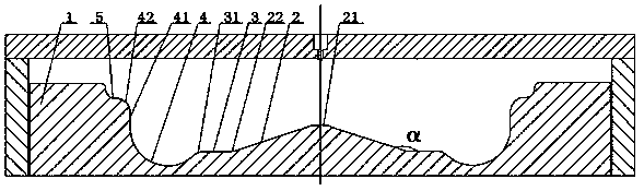
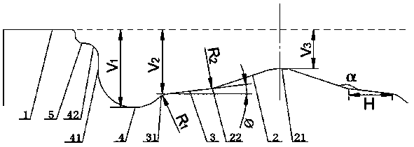
[0048] A low heat loss diesel engine combustion chamber, comprising a cylinder piston 1, the top of the cylinder piston 1 is coaxially provided with a slope guide cone 2 and a lower swirl groove 4; the lower swirl groove 4 and the slope guide cone 2 There is a diversion step surface 3 between them, and the angle α between the diversion step surface 3 and the slope diversion cone surface 2 is 120°-165°; between the lower vortex groove 4 and the top surface of the cylinder piston 1 The maximum distance is V1, the maximum distance between the guide step surface 3 and the top surface of the cylinder piston 1 is V2, the minimum distance between the spherical crown boss 21 and the top surface of the cylinder piston 1 is V3, V1 and The ratio between V2 is 1.05-1.5, and the ratio between V2 and V3 is 1.3-2.5; the projection width H of the guide step surface 3 on the top surface of the cylinder piston 1 is 1mm-6mm; the slope guide The conical surface 2 is connected to the inner circumf...

Embodiment 2

[0050] Embodiment 2 is basically the same as Embodiment 1, and its difference is:

[0051] The included angle ø between the diversion step surface 3 and the top surface of the cylinder piston 1 is 0°-30°; the inner arc surface of the first diversion arc 22 is tangent to the slope diversion cone surface 2, so The outer arc surface of the first diversion arc 22 is tangent to the diversion step 3, and the radius R2 of the circle where the section of the first diversion arc 22 is located is 1mm-6mm; the inner arc of the second diversion arc 31 The surface is tangent to the diversion step 3, the outer arc surface of the second diversion arc 31 is tangent to the inner arc surface of the lower vortex groove 4, and the radius R1 of the circle where the section of the second diversion arc 31 is located is 1mm -6mm.

Embodiment 3

[0053] Embodiment 3 is basically the same as Embodiment 2, and its difference is:

[0054] The guide step surface 3 is parallel to the top surface of the cylinder piston 1 .


PUM


Abstract

A low-heat-loss diesel engine combustor structure comprises an air cylinder piston; a slope flow guiding conical surface and a lower vortex groove are coaxially formed in the top of the air cylinder piston; a flow guiding step surface is arranged between the lower vortex groove and the slope flow guiding conical surface; the included angle alpha between the flow guiding step surface and the slopeflow guiding conical surface is 120 degrees to 165 degrees; the included angle phi between the flow guiding step surface and the top surface of the air cylinder piston is 0 to 30 degrees; upper vortexgroove is formed in the portion, outside the lower vortex groove, of the top of the air cylinder piston; the projection width H of the flow guiding step surface on the top surface of the air cylinderpiston is 1 mm to 6 mm; the slope flow guiding conical surface is connected with the inner circumference of the flow guiding step surface through a first flow guiding arc; and the outer circumferenceof the flow guiding step surface is connected with the lower vortex groove through a second flow guiding arc. Through the design, fuel and flame can expand to the middle of a combustor, fuel is combusted fully, a high temperature region at the bottom of the piston moves to the middle of the combustor, and thus heat loads and heat transfer losses of the combustor are reduced.

Description

technical field [0001] The invention relates to the field of engines, in particular to a combustion chamber structure of a diesel engine with low heat loss, which is particularly suitable for reducing the heat transfer loss in the cylinder, improving the thermal efficiency of the engine, and improving the fuel economy. Background technique [0002] With the rise of fuel prices and the upgrading of emission regulations, the requirements for the economical emission of diesel engines are getting higher and higher. The combustion chamber is a key component of the diesel engine, and the shape of the combustion chamber has an important influence on the airflow movement, the formation and combustion of the mixture in the cylinder of the diesel engine. Promoting the full mixing of oil and gas and improving the air utilization rate through the optimization of the combustion chamber structure is of great significance for improving the thermal efficiency of diesel engines, improving fu...

Claims


Application Information

Patent Timeline
Patent Type & Authority Applications(China)
IPC IPC(8): F02B23/06F02F3/26
CPCF02B23/06F02B23/0624F02B23/0678F02F3/26Y02T10/12
Inventor 刘启胜余宏峰张导龑殷勇
Owner DONGFENG COMML VEHICLE CO LTD
Why Eureka
Try Eureka