


Quick Research
Generate reliable direction feasibility study reports for your R&D in just a few steps.

Technical Q&A
Discover and master advanced knowledge NOW. Basics, ideas, possibilities, all at once.

Find Solutions
As an expert in R&D theories, this can generate solutions to your technical problems instantly.

Evaluate Feasibility
Analyze your overall solution with one click, know your potential R&D risks in advance.

Monitor Landscape
Get weekly tech updates, stay abreast of the latest tech innovations and key insights.
Central cold and heat transforming machine
A kind of good fortune, hot and cold technology, which is applied in the field of cold and hot good fortune machines in Zhonghuan, can solve the problems of low mechanical efficiency, overhaul and maintenance, resource waste, etc., and achieve the effect of improving mechanical efficiency, reducing mechanical friction and saving energy
- Summary
- Abstract
- Description
- Claims
- Application Information
AI Technical Summary
Problems solved by technology
Method used
Image

Examples
Embodiment 1
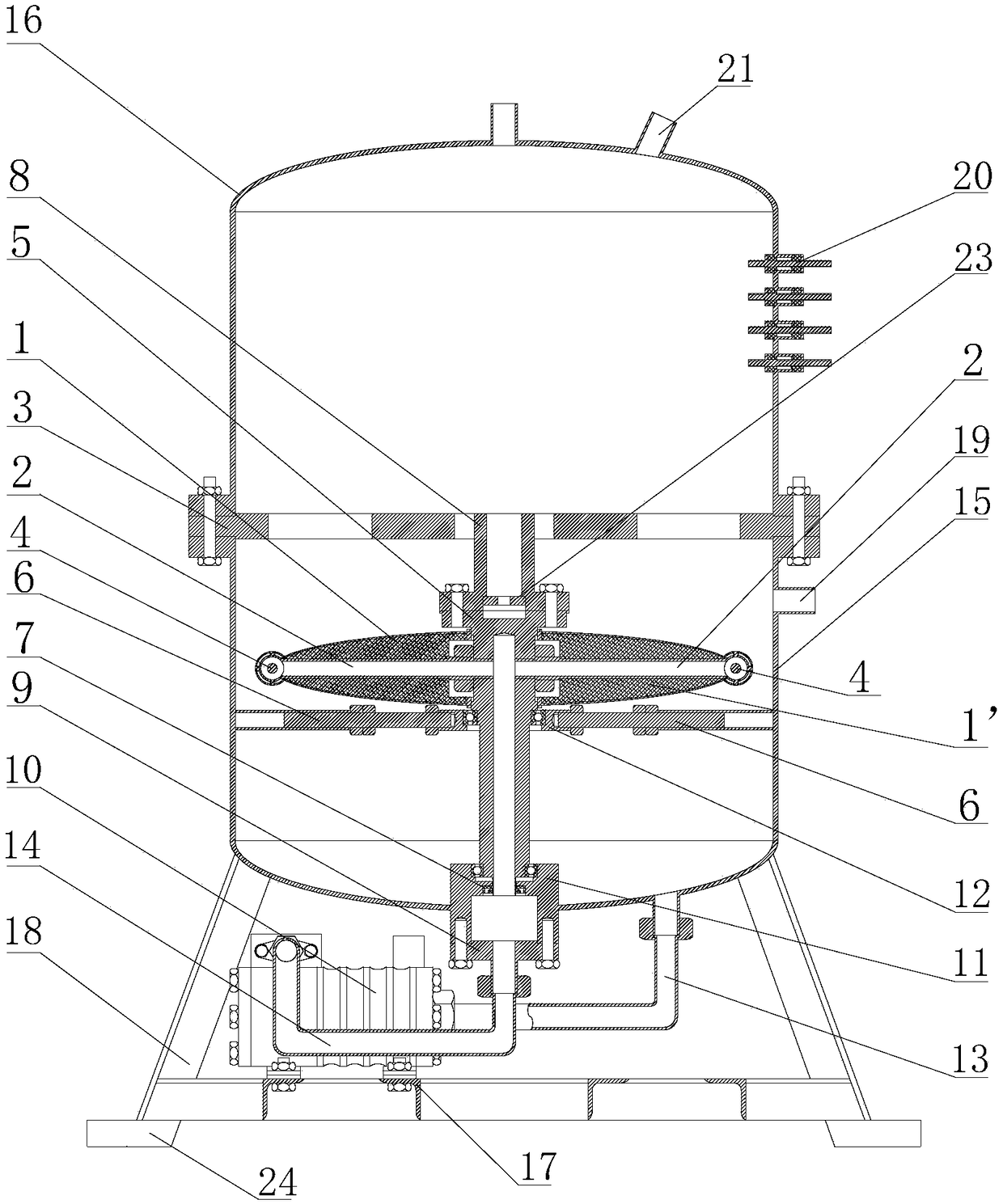
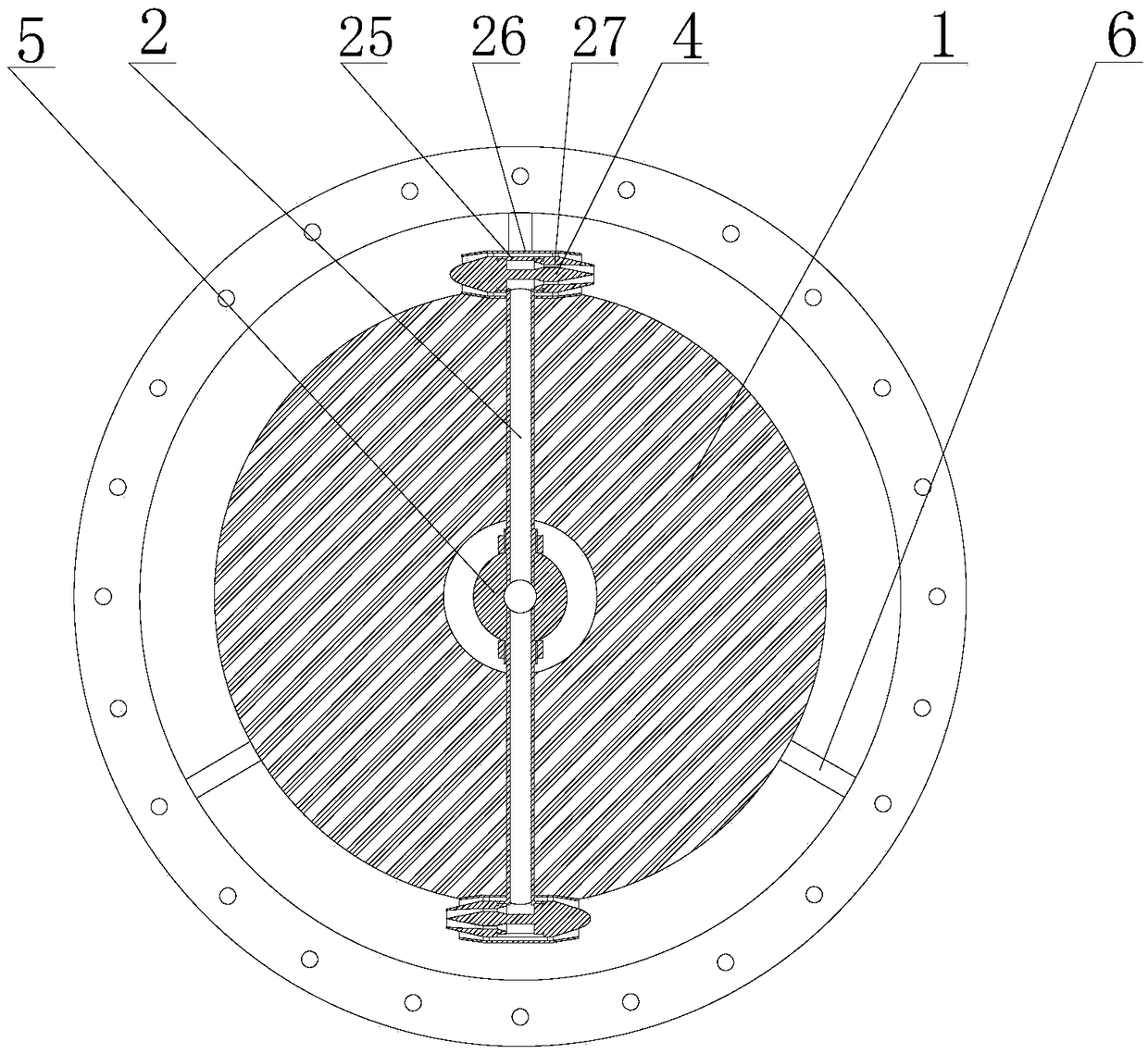
[0029] Such as figure 1 , figure 2 As shown, this embodiment discloses a middle-ring cold and heat making machine, which includes a frame, a container arranged on the frame, a pump 10 arranged on the frame, and a power discharger arranged in the container. The frame It is used to support a fixed container. Both the output port and the input port of the pump are connected with the container, and a circulating circulation line is formed between the pump and the container. The power discharger is located in the container, and is used to release the pumped fluid to facilitate cooling of the fluid. Specifically, the container includes an upper container 16 and a lower container 15, the lower container is connected and fixed to the frame body, and the lower container is provided with a main shaft 5, and an overflow passage is provided inside the main shaft; the power discharger It is socketed on the main shaft, and the power discharger is equipped with a channel lever 2, and the c...
Embodiment 2
[0056] This embodiment discloses a central cold and heat generator, which includes a frame body, a container arranged on the frame body, a pump arranged on the frame body, and a power discharger arranged in the container. In order to support the fixed container, the output port and the input port of the pump are connected with the container, and a circulating circulation line is formed between the pump and the container. The power discharger is located in the container, which is used to release the pumped fluid to facilitate the cooling of the fluid. Specifically, the container includes an upper container and a lower container, the lower container is connected and fixed to the frame body, and a main shaft is provided in the lower container, and an overflow channel is provided inside the main shaft; the power discharger is sleeved on the On the main shaft, and the power discharger is equipped with a channel lever, and the channel lever is provided with an outflow channel, one po...
Embodiment 3
[0062] This embodiment discloses a central cold and heat generator, which includes a frame body, a container arranged on the frame body, a pump arranged on the frame body, and a power discharger arranged in the container. In order to support the fixed container, the output port and the input port of the pump are connected with the container, and a circulating circulation line is formed between the pump and the container. The power discharger is located in the container, which is used to release the pumped fluid to facilitate the cooling of the fluid. Specifically, the container includes an upper container and a lower container, the lower container is connected and fixed to the frame body, and a main shaft is provided in the lower container, and an overflow channel is provided inside the main shaft; the power discharger is sleeved on the On the main shaft, and the power discharger is equipped with a channel lever, and the channel lever is provided with an outflow channel, one po...
PUM
 Abstract
Description
Claims
Application Information
 - R&D Engineer
- R&D Manager
- IP Professional
- Industry Leading Data Capabilities
- Powerful AI technology
- Patent DNA Extraction
Browse by: Latest US Patents, China's latest patents, Technical Efficacy Thesaurus, Application Domain, Technology Topic, Popular Technical Reports.
© 2024 PatSnap. All rights reserved.Legal|Privacy policy|Modern Slavery Act Transparency Statement|Sitemap|About US| Contact US: help@patsnap.com