A control method and cooling device for charging and cooling an energy storage unit

A technology of an energy storage unit and a control method, which is applied to household refrigeration devices, packaging, applications, etc., and can solve problems such as inability to charge cold, and no charging time control under cold charging conditions, so as to avoid waste of cold energy and realize reasonable application Effect

Active Publication Date: 2020-08-25
CRRC SHIJIAZHUANG CO LTD +1
View PDF11 Cites 0 Cited by
  • Summary
  • Abstract
  • Description
  • Claims
  • Application Information

AI Technical Summary

Problems solved by technology

However, the cooling working condition of this patent has no cooling time control, and it cannot be reasonably charged according to the use requirements.

Method used


Image

  • A control method and cooling device for charging and cooling an energy storage unit
  • A control method and cooling device for charging and cooling an energy storage unit
  • A control method and cooling device for charging and cooling an energy storage unit

Examples


no. 1 example

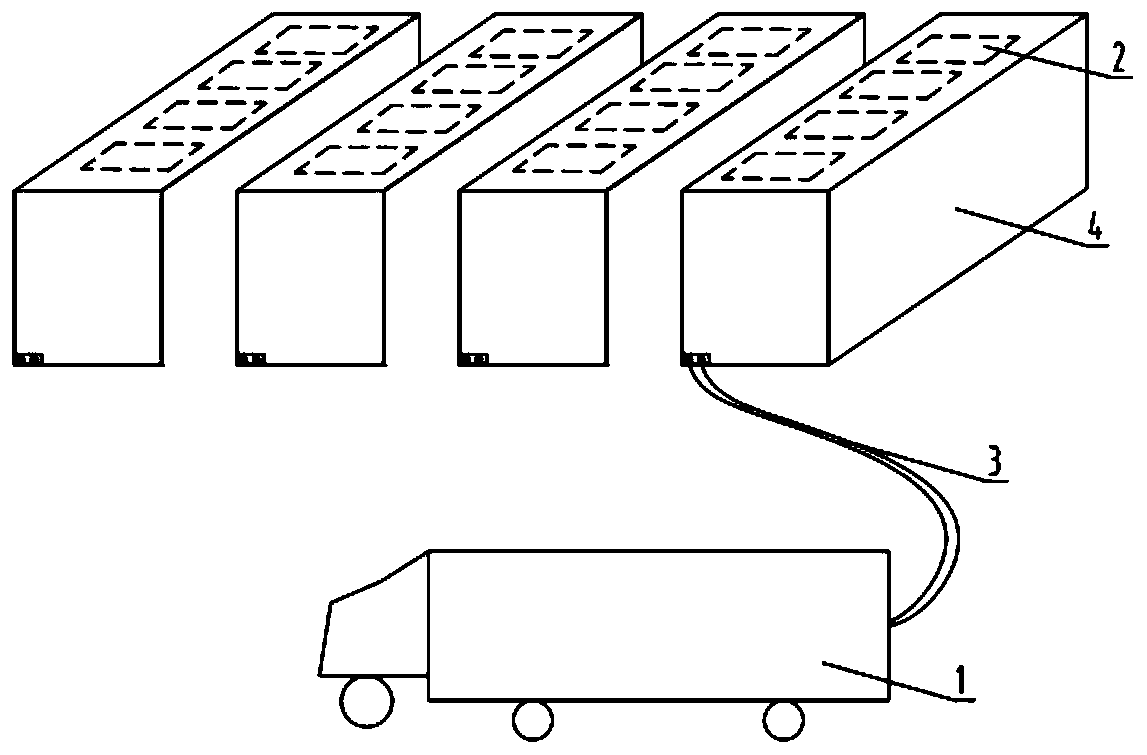
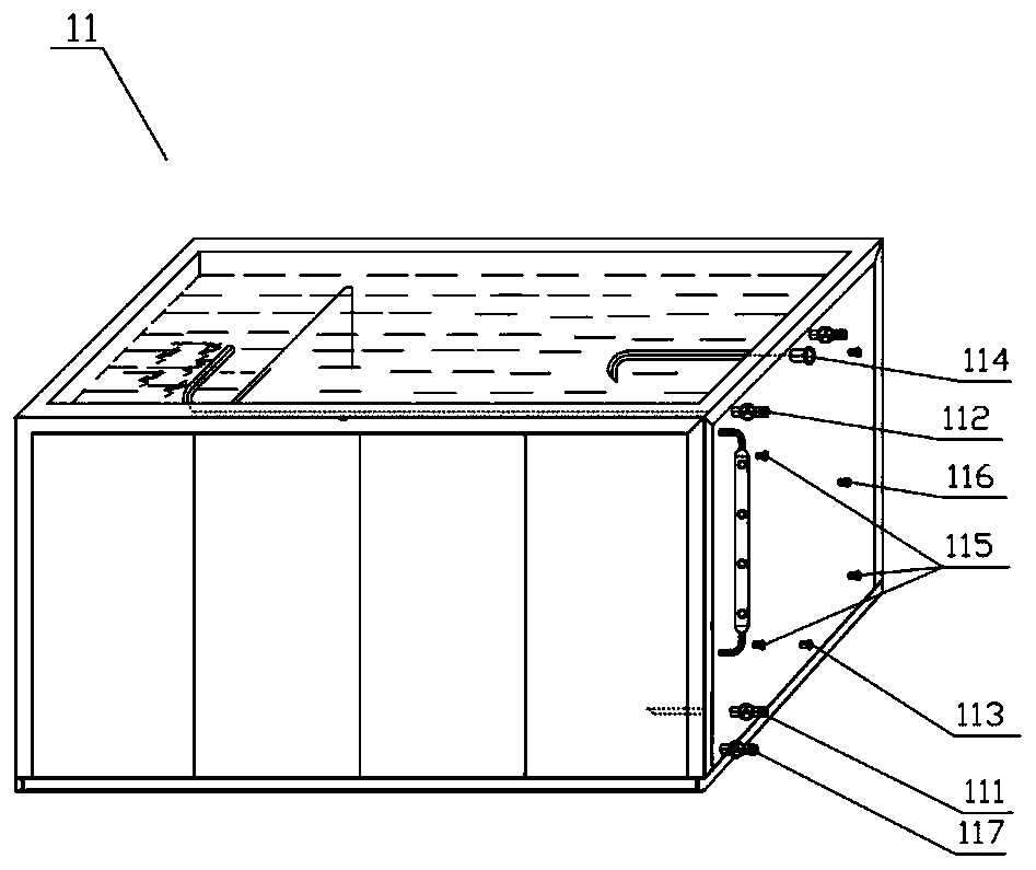
[0062] The first embodiment: detecting the temperature difference between the brine charging inlet 111 and the brine charging outlet 112 to determine the first cooling period. Use the second temperature measuring probe 126 in the cooling device to measure the temperatures of the cooling liquid inlet 111 and the cooling outlet 112 respectively, when the temperatures of the cooling inlet 111 and the cooling outlet 112 are When the difference is less than a predetermined value, the cooling device 1 stops charging the energy storage unit 2 in the container 4;

no. 2 example

[0063] The second embodiment: detect the predetermined cooling capacity saturation degree of the energy storage unit 2 to determine the first period of cooling, if the predetermined cooling capacity saturation of the energy storage unit 2 is reached, the cooling device 1 stops feeding the container 4 The energy storage unit 2 is charged cold;

no. 3 example

[0064] The third embodiment: determine the first period of cold charging according to the predetermined work demand of the energy storage unit 2, and its work demand is determined according to the path planning data given by the path planning module of the energy storage unit 2, and the path planning data includes the cooling time data and / or charge capacity data.

[0065] The above three embodiments can be used alone or in combination.

[0066] The above steps 1), 2), and 3) are cooling steps Z, and the above steps 4), 5), and 6) are cooling step C, and cooling step C and cooling step Z can be performed simultaneously or separately. The refrigerating step Z also includes a fault detection step. When the compressor pressure in the refrigerating unit 12 exceeds a preset range, the PLC control device judges that there is a fault, and the refrigerating step stops.

[0067] Image 6 It is a flow chart of the refrigeration steps. In order to prepare the coolant solution at differ...


PUM


Abstract

A control method for supplying cold energy to an energy storage unit (2) by means of a cold energy supplying device (1), the control method comprising the following steps: in a cold energy supplying starting step, starting the cold energy supplying device (1); in a connection step, connecting the cold energy supplying device (1) to the energy storage unit; and in a cold energy supplying step, supplying cold energy to the energy storage unit by means of the cold energy supplying device (1) for a first time period, the first time period being determined on the basis of a preset cold energy supplying condition. Said control method controls the refrigerant charging duration on the basis of the preset refrigerant charging condition, such that reasonable refrigerant charging can be realized according to requirements of different energy storage units.

Description

technical field [0001] The invention relates to an insulated transportation system, in particular to a control method and a cooling device for charging an energy storage unit with cold. Background technique [0002] Fresh products such as vegetables and fruits, processed foods such as quick-frozen foods and dairy products, and various injections, medicines, vaccines and other pharmaceuticals should always be under the specified temperature environment during production, storage, transportation, sales, and consumption. The storage and transportation of these items must rely on special equipment. With the different types of transported items, the temperature maintained in the special equipment is different. In order to ensure the specified temperature in the special equipment, the special equipment needs a cooling device to charge it. [0003] Patent CN102183114A discloses a cold charging method for cold storage materials, which includes the following steps: (1) Low temperatu...

Claims


Application Information

Patent Timeline
Patent Type & Authority Patents(China)
IPC IPC(8): F28D20/02B65D90/00B60P3/20B60H1/32F25D11/00F25D13/00
CPCB60H1/3201B60P3/20B65D90/00F25D11/00F25D13/00F28D20/02Y02E60/14
Inventor 廖良金丁玉龙陶樯胡晓微聂彬剑童山虎
Owner CRRC SHIJIAZHUANG CO LTD
Why Eureka
Try Eureka