Optical fiber device and detection method and detection equipment thereof

An optical fiber device and detection method technology, which is applied in the field of optical fiber device detection and communication, can solve the problems of unimproved product performance, low efficiency and accuracy, and high product defect rate, and achieves detection efficiency and high degree of automation. Wide range of highly automated effects

Active Publication Date: 2019-01-08
ANHUI PENGDA OPTOELECTRONICS TECH CO LTD
View PDF6 Cites 5 Cited by
  • Summary
  • Abstract
  • Description
  • Claims
  • Application Information

AI Technical Summary

Problems solved by technology

The existing equipment detects fewer items and requires manual loading and unloading
[0003] The shortcomings of the existing equipment are: 1. A set of equipment can only detect a certain performance parameter, and cannot realize automatic multi-functional detection; 2. The disassembly and assembly of the end protection cover needs to be completed manually, and the production efficiency is

Method used


Image

  • Optical fiber device and detection method and detection equipment thereof
  • Optical fiber device and detection method and detection equipment thereof
  • Optical fiber device and detection method and detection equipment thereof

Examples


Embodiment Construction

[0042] The present invention will be further described below in conjunction with the accompanying drawings and embodiments.

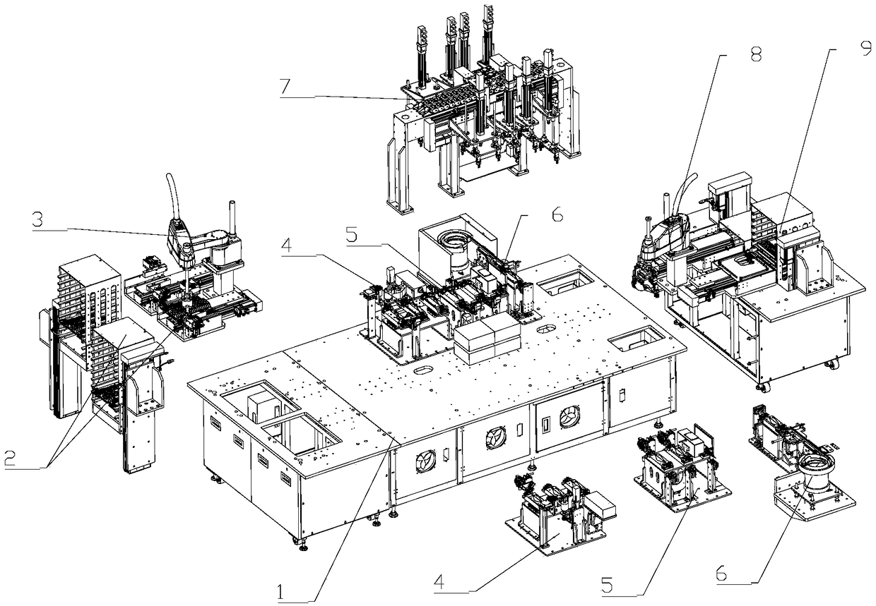
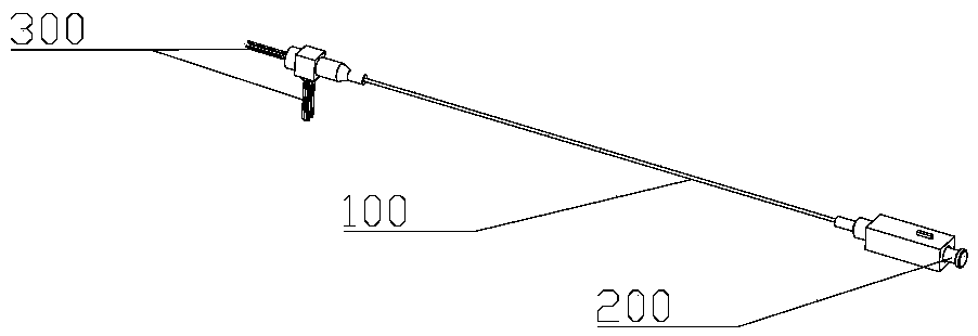
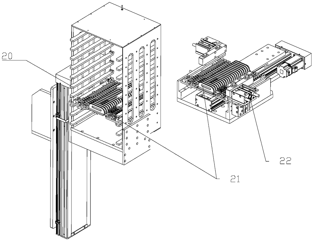
[0043] Such as figure 1 As shown, the optical fiber device testing equipment includes a frame 1 and a feeding device 2 installed on it, a feeding manipulator device 3, a pre-test carding module 4, an optical fiber device performance testing module 5, a protective cover device 6, Stepping and carrying device 7, folding and placing manipulator device 8 and unloading device 9.

[0044] The feeding device 2 is connected with the carding module 4 before detection through the feeding manipulator device 3 . The pre-test carding module 4, the optical fiber device performance test module 5 and the protective cover installation device 6 are sequentially connected. The position of the stepping and conveying device 7 corresponds to the carding module 4 before detection, the optical fiber device performance detection module 5 and the protective cover installation ...


PUM


Abstract

The invention relates to the technical field of communication. A detection method for an optical fiber device comprises the following steps of carrying out feeding, carrying out combing before detection, carrying out detection, assembling a protection cover and carrying unloading. The detection method for the optical fiber device has the advantages that detection efficiency and automation degree are high and a test range is wide.

Description

technical field [0001] The invention relates to the technical field of communication, in particular to the field of optical fiber device detection. Background technique [0002] Optical fiber communication test refers to the test work to verify the characteristics of optical fiber communication system. There are many items to be carried out, including the full attenuation of optical fiber line, the output optical power of optical transmitter, the sensitivity of optical receiver, dynamic range, signal jitter, and light transmission ability test Wait. The existing equipment detects fewer items and requires manual loading and unloading. [0003] The shortcomings of the existing equipment are: 1. A set of equipment can only detect a certain performance parameter, and cannot realize automatic multi-functional detection; 2. The disassembly and assembly of the end protection cover needs to be completed manually, and the production efficiency is low ;3. The end of the optical fibe...

Claims


Application Information

Patent Timeline
IPC IPC(8): G01M11/00G01B21/30
CPCG01B21/30G01M11/30
Inventor 吴美珍
Owner ANHUI PENGDA OPTOELECTRONICS TECH CO LTD
Why Eureka
Try Eureka