Fluorescence imaging method and device

A fluorescence imaging and laser device technology, applied in the field of fluorescence imaging, can solve problems such as weak fluorescence signal intensity

Inactive Publication Date: 2019-01-08
LASER FUSION RES CENT CHINA ACAD OF ENG PHYSICS
View PDF12 Cites 0 Cited by
  • Summary
  • Abstract
  • Description
  • Claims
  • Application Information

AI Technical Summary

Problems solved by technology

[0004] In view of this, the present application provides a fluorescence imaging method and device, which are used to solve the problem of weak fluorescence signal intensity in the fluorescence imaging technology based on large and powerful laser devices in the prior art

Method used


Image

  • Fluorescence imaging method and device
  • Fluorescence imaging method and device
  • Fluorescence imaging method and device

Examples


no. 1 example

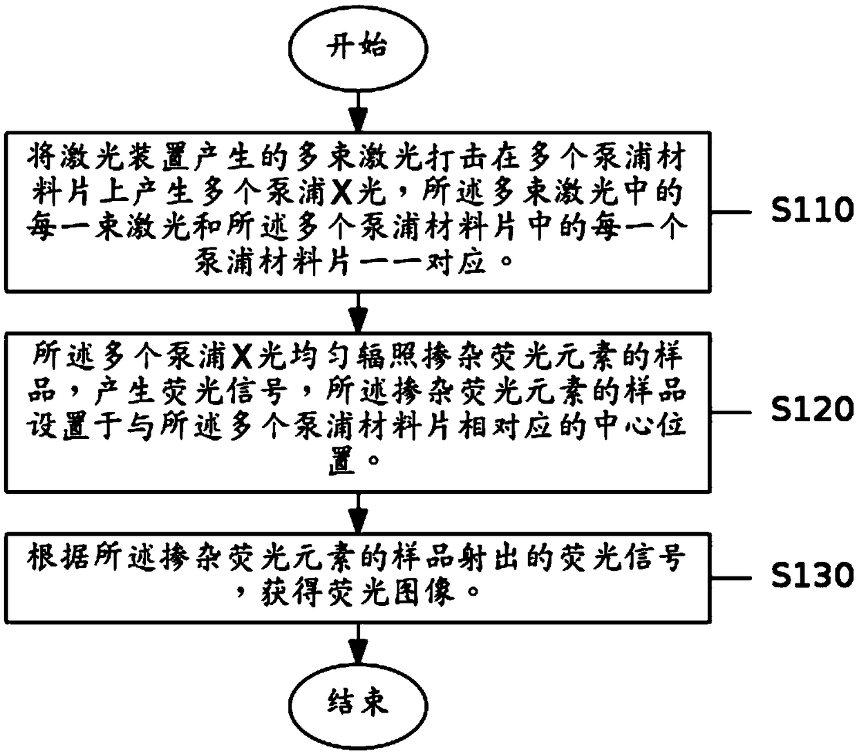
[0031] See figure 1 , figure 1 A schematic flowchart of the fluorescence imaging method provided by the embodiment of the present application is shown. The application provides a fluorescence imaging method, the fluorescence imaging method comprising:

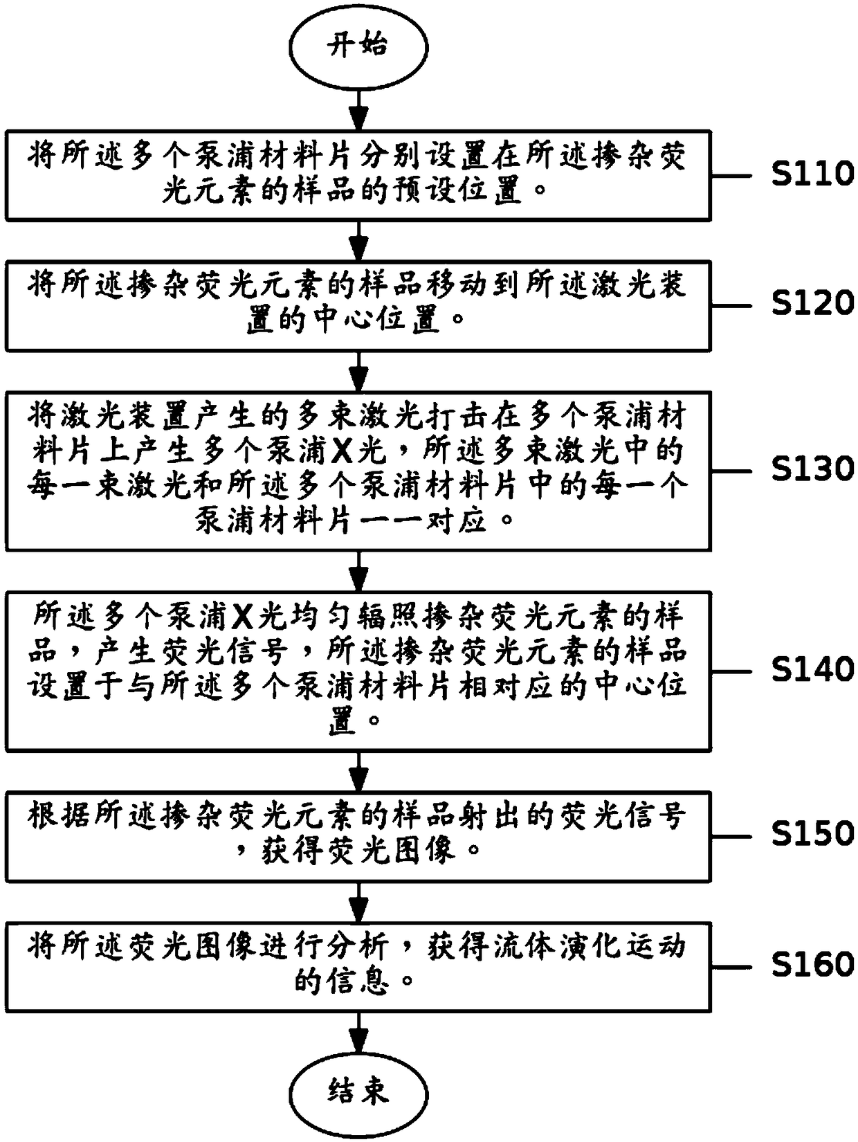
[0032] Step S110: strike multiple laser beams generated by the laser device on multiple pump material sheets to generate multiple pump X-rays, each of the multiple laser beams and each of the multiple pump material sheets There is a one-to-one correspondence with one pump material sheet.

[0033] Among them, what needs to be explained is that, using the characteristics of isotropy of fluorescence emission, abandoning the traditional concept of using a single or multiple laser beams to superimpose to generate a pump source, the multiple pump laser beams are dispersed, and each laser beam generates its own An independent pump source. Each laser beam is in one-to-one correspondence with each pump material sheet, and in this wa...

no. 2 example

[0059] See Figure 4 , Figure 4 A schematic structural diagram of the fluorescence imaging device provided by the embodiment of the present application is shown. The present application also provides a fluorescence imaging device 101, the fluorescence imaging device 101 includes: a laser device 100, a plurality of pump material sheets 200, a sample 300 doped with fluorescent elements, and an imaging recording device 400; a plurality of pump material sheets 200 Set around the sample 300 doped with fluorescent elements, the sample 300 doped with fluorescent elements is set at the central position corresponding to a plurality of pumping material sheets 200, and the imaging and recording device 400 is set to receive the light emitted from the sample 300 doped with fluorescent elements The location of the fluorescent signal.

[0060] Among them, it should be noted that the fluorescence imaging device 101 includes: a laser device 100, a plurality of pumping material sheets 200, a...


PUM

PropertyMeasurementUnit
Power densityaaaaaaaaaa

Abstract

The invention provides a fluorescence imaging method and device and aims at solving the problem of weak fluorescence signal intensity in a fluorescence imaging technology based on a large intense laser device in the prior art. The fluorescence imaging method comprises steps as follows: multiple beams of laser produced by a laser device are struck on multiple pumping material sheets, multiple pumping X-rays are produced, and the multiple beams of laser are in one-to-one correspondence with the multiple pumping material sheets; the multiple pumping X-rays uniformly irradiate a sample doped withfluorescent elements, fluorescence signals are produced, and the sample doped with fluorescent elements is arranged in the center corresponding to the multiple pumping material sheets; a fluorescenceimage is obtained according to the fluorescence signals emitted by the sample doped with the fluorescent elements.

Description

technical field [0001] The present application relates to the technical field of fluorescence imaging, and relates to a fluorescence imaging method and device. Background technique [0002] At present, it is the most widely used means in the world to use large-scale powerful laser devices to carry out corresponding R&D and research in the industry. Among them, X-ray backlight photography is the most mature technology, and X-rays are also called X-rays. The flow of particles produced by the transition between two energy levels with greatly different energies is an electromagnetic wave with a wavelength between ultraviolet rays and gamma rays. [0003] X-ray fluorescence imaging uses laser targeting to generate hard X-rays as a pump source to excite the fluorescent signal of the tracer elements in the sample to be studied, and obtains the spatial position of the tracer elements through X-ray fluorescence imaging, thereby inferring the position of the sample under loading condi...

Claims


Application Information

Patent Timeline
IPC IPC(8): G01N21/64
CPCG01N21/6456
Inventor 晏骥陈忠靖蒋炜涂绍勇蒲昱东姚立张兴黄天晅陈黎
Owner LASER FUSION RES CENT CHINA ACAD OF ENG PHYSICS
Why Eureka
Try Eureka