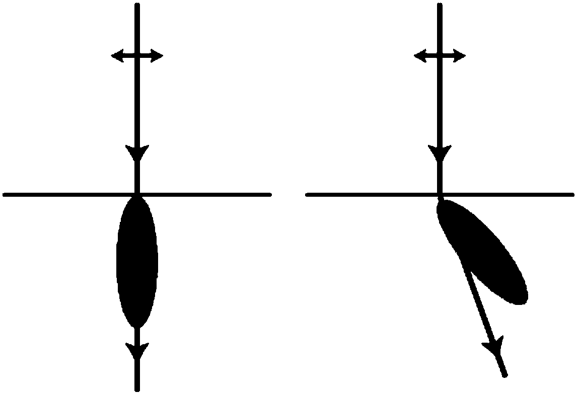
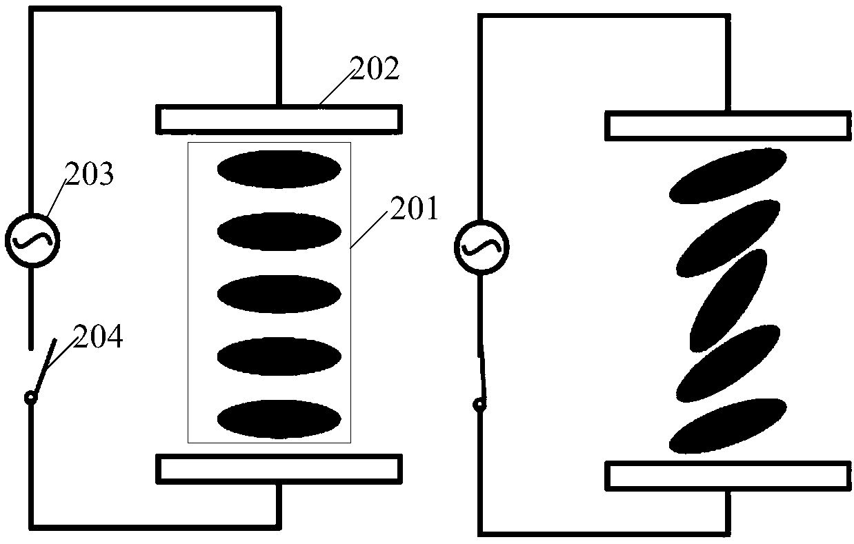
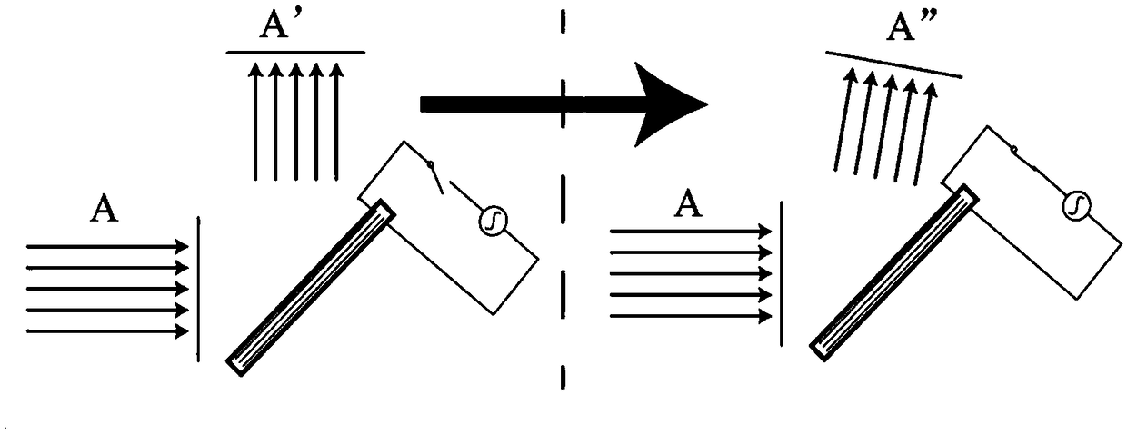
Scanning device and laser radar

A laser radar and scanning device technology, applied in the field of optics, can solve the problems of reducing the accuracy and stability of the mechanical rotation scanning structure, shortening the life of the mechanical rotation scanning structure, wear and tear of the mechanical rotation scanning structure, etc.

Pending Publication Date: 2019-01-08
BENEWAKE BEIJING TECH CO LTD
View PDF0 Cites 14 Cited by
  • Summary
  • Abstract
  • Description
  • Claims
  • Application Information

AI Technical Summary

Problems solved by technology

[0004] However, due to the mechanical rotation of the mechanical rotation scanning structure, as the mechanical rotation continues for a long time, the mechanical rotation scanning structure will be continuously worn, thereby shortening the life of the mechanical rotation scanning structure, and with the generation of wear, it will also reduce the mechanical capacity. Accuracy and stability of rotating scanning structures

Method used


Image

  • Scanning device and laser radar
  • Scanning device and laser radar
  • Scanning device and laser radar

Examples


Embodiment Construction

[0040] The following will clearly and completely describe the technical solutions in the embodiments of the application with reference to the drawings in the embodiments of the application. Apparently, the described embodiments are only some of the embodiments of the application, not all of them. Based on the embodiments in this application, all other embodiments obtained by persons of ordinary skill in the art without making creative efforts belong to the scope of protection of this application.

[0041] The scanning structure used in the traditional laser radar is mainly a mechanical rotation scanning structure. Due to the mechanical rotation of this scanning structure, with the continuous mechanical rotation for a long time, the mechanical rotation scanning structure is continuously worn, thereby shortening the mechanical rotation scanning time. The life of the structure, and with the generation of wear, it will also reduce the accuracy and stability of the mechanical rotati...


PUM


Abstract

The embodiment of the application provides a scanning device and a laser radar. The scanning device comprises a light source, a polarizer, a liquid crystal structure and an electrical structure; the light source emits a laser beam to the liquid crystal structure; the liquid crystal structure receives the laser beam, and reflects the laser beam through a reflecting plane of the liquid crystal structure, the reflected laser beam forms a light spot on a tested object plane, and the liquid crystal structure is located in an electric field. When the laser radar with the scanning device is used forperforming scanning measurement on to-be-tested object plane, the electrical structure forms the electric field by applying the voltage in the preset rule. on the liquid crystal structure; since the liquid crystal structure has a certain mobility, an internal molecule of the liquid crystal structure can produce corresponding deflection when the voltage is applied to the liquid crystal structure, the refractive rate of the liquid crystal structure reflecting plane is changed, thereby changing an exit direction of the laser beam after passing through the reflecting plane, and then changing the location of the light spot on the tested object plane, and realizing the scanning on the tested object plane. The device is higher in precision and has measurement repeatability, control flexibility and stability.

Description

technical field [0001] The present application relates to the field of optical technology, in particular to a scanning device and a laser radar. Background technique [0002] Lidar is a radar system that emits laser beams to detect characteristic quantities such as the position and speed of targets, and is widely used in various fields. Lidar can be divided into two categories: scanning and non-scanning. For scanning Lidar, scanning Lidar changes the propagation direction of the laser through the scanning structure, so that the laser can be sequentially formed at different positions on the surface of the measured object. The light spot is used to complete the scanning of the surface of the object to be measured. During the scanning process, the reflected light on the surface of the object to be measured is received by the detector of the laser radar to complete the scanning measurement of the surface of the object to be measured. [0003] The scanning structure used in the ...

Claims


Application Information

Patent Timeline
Patent Type & Authority Applications(China)
IPC IPC(8): G01S17/89G01S7/481
CPCG01S17/89G01S7/4817
Inventor 疏达李远杨野郑凯
Owner BENEWAKE BEIJING TECH CO LTD
Why Eureka
Try Eureka