Forming device for machining of motor support

A technology of forming device and motor bracket, which is applied to auxiliary devices, metal processing equipment, manufacturing tools, etc., can solve the problems of time-consuming and laborious processing, affecting motor installation, and inability to guarantee motor stability, and achieves parallelism and verticality. Guarantee, stability guarantee, welding precision effect

Active Publication Date: 2019-01-11
ANHUI RUIYAN NEW MATERIAL TECH RES INST
View PDF8 Cites 2 Cited by
  • Summary
  • Abstract
  • Description
  • Claims
  • Application Information

AI Technical Summary

Problems solved by technology

[0007] (1) The current processing of the motor bracket, because there is no special tooling, cannot guarantee the concentricity of the front and back sides and the parallelism of the two sides. The processing process is time-consuming and laborious, and at the same time affects the use of the machine and product quality;
[0008] (2) The motor bracket cannot be effectively fixed during the assembly and welding process, resulting in the inability to guarantee the parallelism and verticality of the motor bracket, which affects the subsequent installation of the motor, and the stability of the motor during use cannot be guaranteed

Method used


Image

  • Forming device for machining of motor support
  • Forming device for machining of motor support
  • Forming device for machining of motor support

Examples


Embodiment Construction

[0029] The following will clearly and completely describe the technical solutions in the embodiments of the present invention with reference to the accompanying drawings in the embodiments of the present invention. Obviously, the described embodiments are only some, not all, embodiments of the present invention. Based on the embodiments of the present invention, all other embodiments obtained by persons of ordinary skill in the art without making creative efforts belong to the protection scope of the present invention.

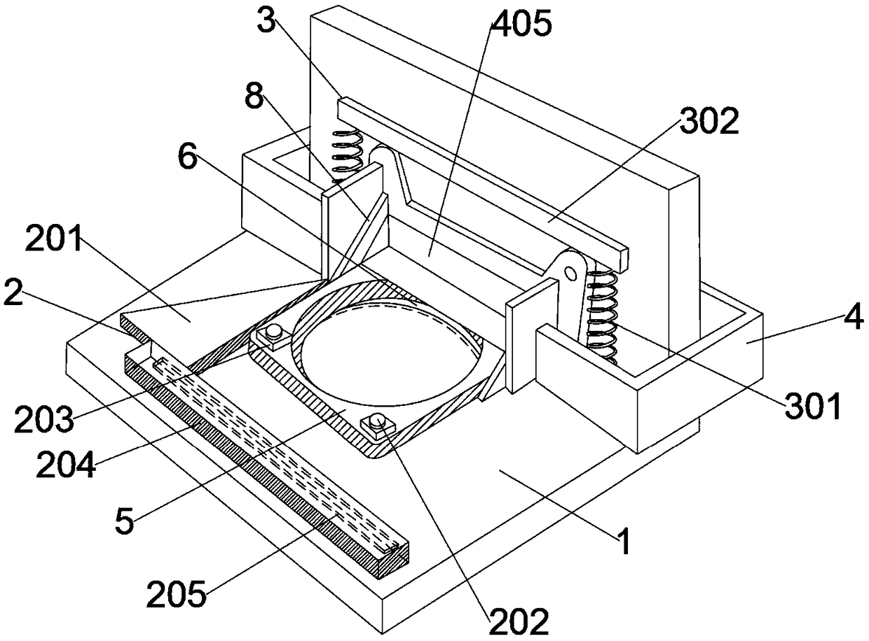
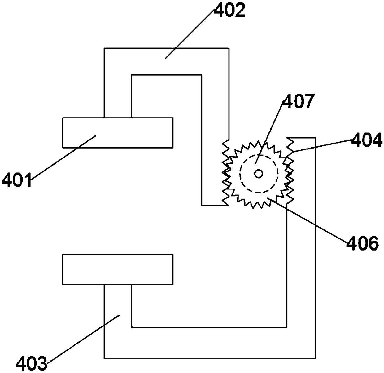
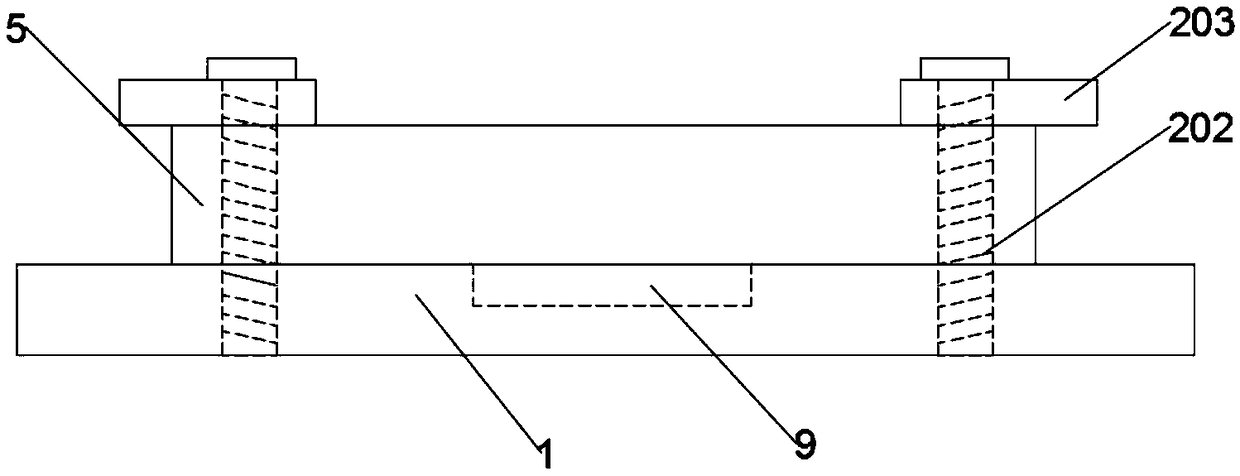
[0030] Such as Figure 1 to Figure 4 As shown, the present invention provides a forming device for processing motor brackets, which includes an L-shaped base plate 1 for fixing the motor base 10 . The motor base 10 includes a frame bottom plate 5, a frame side plate 7 and a side limiting plate 8. The semi-enclosed structure formed by the three plates can place the motor stably therein and be installed in various occasions. The frame bottom plate 5 and the fra...


PUM


Abstract

The invention discloses a forming device for machining of a motor support. The forming device comprises an L-shaped bottom plate, a motor seat is arranged on the L-shaped bottom plate, the motor seatcomprises a machine frame bottom plate, a machine frame side plate and side limiting plates, the machine frame bottom plate and the machine frame side plate are welded in a perpendicular mode, and theside limiting plates are perpendicularly welded to the two sides of the machine frame bottom plate; a horizontal limiting device is arranged on the L-shaped bottom plate, the machine frame bottom plate is arranged on the horizontal limiting device in a sleeving mode, a convex circular ring is arranged on the lower surface of the machine frame bottom plate, and a circular groove for allowing the convex circular ring to be embedded is formed in the L-shaped bottom plate; and the side surface of the L-shaped bottom plate is provided with a vertical limiting device, the machine frame side plate is arranged on the vertical limiting device in a sleeving mode, and the two ends of the side limiting plates are connected with fixing devices. Thus, the concentricity of a front face circle and a backface circle and the parallelism degree of the two faces are guaranteed, and the levelness and the perpendicularity of welding among motor support elements of are improved.

Description

technical field [0001] The invention relates to the field of production of motor supporting facilities, in particular to a forming device for processing motor brackets. Background technique [0002] The motor base is a large number of parts on the machine tool. It belongs to the small box part. Its main function is to connect the servo drive motor and the ball screw. Therefore, the requirements for the manufacturing accuracy and processing efficiency of this part are very high. Its accuracy directly affects the accuracy and performance of the machine tool. Accelerating the processing speed of the motor base and reducing the processing cost of the motor base can increase the competitive advantage of the machine tool. The parts that support or accommodate parts in the machine are called racks. The motor base is a kind of rack. The design should take into account the characteristic rigidity, strength and stability that the rack design needs to ensure, and also meet the require...

Claims


Application Information

Patent Timeline
Patent Type & Authority Applications(China)
IPC IPC(8): B23K37/04
CPCB23K37/0443
Inventor 李大伟
Owner ANHUI RUIYAN NEW MATERIAL TECH RES INST
Why Eureka
Try Eureka