Ceramic membrane tube machining equipment

A ceramic membrane tube and processing equipment technology, which is applied in stone processing equipment, metal processing equipment, grinding/polishing equipment, etc., can solve problems such as heavy workload, low efficiency, and easy product problems, and achieve heavy workload, The effect of small workload and convenient operation

Pending Publication Date: 2019-01-11
HENAN UNIVERSITY OF TECHNOLOGY
View PDF6 Cites 0 Cited by
  • Summary
  • Abstract
  • Description
  • Claims
  • Application Information

AI Technical Summary

Problems solved by technology

This method is very mature, but the efficiency is low, the workload is heavy, and the product processing position and the unprocessed position form a straight platform, there is no transition zone, and the product is prone to problems during use
However, in the current situation, there is no better way or equipment to solve the above problems

Method used


Image

  • Ceramic membrane tube machining equipment
  • Ceramic membrane tube machining equipment
  • Ceramic membrane tube machining equipment

Examples


Embodiment 1

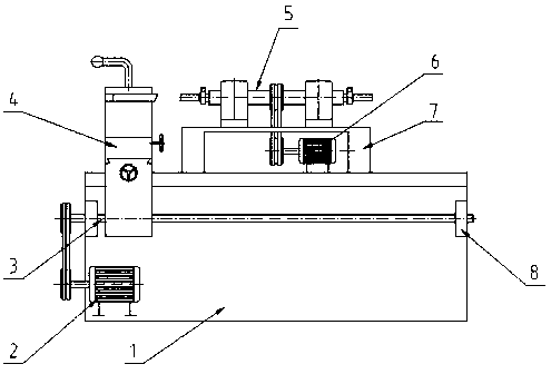
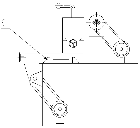
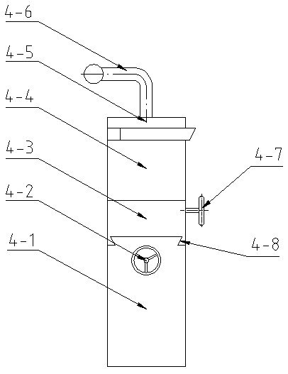
[0051] see Figure 1-12, in the figure, a ceramic membrane tube processing equipment, including a bed 1, a traveling mechanism 4, a spindle mechanism 5, a spindle holder 7, a drive motor 2, a spindle motor 6, a screw 3 and a screw bearing 8. A high-precision trapezoidal table guide rail 9 is set on the bed, and the traveling mechanism is set on the guide rail. There are screw holes 4-1-1 at the lower part of the traveling mechanism. Above; the spindle mechanism is fixed on the spindle fixing seat, and the spindle fixing seat is fixed on the bed, and the corresponding fixing method is bolt or welding; the screw and the driving motor, the spindle mechanism and the spindle motor are connected by a pulley and a belt, and the spindle motor is fixed by a bolt on the bed. The traveling mechanism includes a walking slider 4-1, a feed slider 4-3, a tool holder slider 4-4, a tool holder 4-5, a rotating handle 4-6, a feed handwheel 4-2 and a fine-tuning handwheel 4 -7. Set trapezoidal...

Embodiment 2

[0054] see Figure 13-14 , among the figure, grinder cutter 12 or grinder 13 are installed on the knife rest slide block. In this embodiment, a cutting machine or a grinding wheel can also be used to cut or grind the end of the ceramic membrane tube.

Embodiment 3

[0056] see Figure 15 , in the figure, the spindle motor 6 is fixed below the bed 1. This embodiment increases the aesthetics of the equipment on the one hand, and increases the safety on the other hand. At the same time, it prevents dust from eroding the motor shaft and protects the motor.


PUM


Abstract

The invention discloses special equipment for machining a ceramic membrane tube. The equipment comprises a lathe body, a travelling mechanism, a main shaft mechanism, a main shaft fixing seat, a driving motor, a main shaft motor, a lead screw and lead screw bearing blocks. A high-precision trapezoidal table guide rail is arranged on the lathe body, the travelling mechanism is arranged on the guiderail, a screw hole is formed in the lower portion of the travelling mechanism, the screw hole is matched with the lead screw, and the lead screw is fixed on the lead screw bearing blocks on the two sides of the lathe body; the main shaft mechanism is fixed on the main shaft fixing seat, the main shaft fixing seat is fixed on the lathe body, and the corresponding fixing mode is a bolt fixing modeor a welding mode; the lead screw and the driving motor are connected through a belt wheel and a belt, the main shaft mechanism and the main shaft motor are connected through a belt wheel and a belt,and the main shaft motor is fixed on the lathe body through bolts; and a lathe tool is arranged on the travelling mechanism. According to the equipment, the travelling mechanism is used for driving the lathe tool to run, so that the machining of the ceramic membrane tube is realized. The equipment has the advantages of being reasonable in structure and convenient to operate, one-time clamping of two ends for machining is realized, the machining precision and coaxiality of products are guaranteed, and the workload of workers is reduced.

Description

technical field [0001] The invention belongs to the technical field of ceramic membrane tube processing, and in particular relates to ceramic membrane tube processing equipment. Background technique [0002] For the industrial application of ceramic membrane tubes, the first problem that needs to be solved is the end sealing, which requires precision machining at both ends of the ceramic membrane tubes. Ceramic membrane tube processing is divided into end cutting and end outer circle processing. The purpose of cutting the end is to ensure the usable size of the product; the purpose of the outer circle processing of the end is to correct the coaxiality of both ends, which is convenient for installation, and at the same time ensure the roundness and surface finish of the outer circumference of the end, which is convenient for reliable sealing and safe operation after installation. At present, in the industry, the commonly used processing method is to first cut the end with a ...

Claims


Application Information

Patent Timeline
Patent Type & Authority Applications(China)
IPC IPC(8): B24B27/06B24B55/06B24B5/04B24B41/06B24B47/20B28D1/16B28D7/04B28D7/02
CPCB24B5/04B24B27/06B24B41/06B24B47/20B24B55/06B28D1/16B28D7/02B28D7/04
Inventor 魏杰李彦涛王庆伟马秋花
Owner HENAN UNIVERSITY OF TECHNOLOGY
Why Eureka
Try Eureka