Shot blasting machine for removing metal edges and corners

A technology of shot blasting machine and edges and corners, which is applied in the direction of metal processing equipment, surface polishing machine tools, machine tools suitable for grinding workpiece edges, etc., which can solve problems such as high price, product scrapping, and environmental damage on the production site, and improve the quality of finished products. High efficiency, strong practicability, and convenient production

Inactive Publication Date: 2019-01-11
高飞
View PDF6 Cites 1 Cited by
  • Summary
  • Abstract
  • Description
  • Claims
  • Application Information

AI Technical Summary

Problems solved by technology

[0002] At present, for some metal semi-finished products with edges, corners, edges, burrs, and top cones that affect the production of the next process, sand grinding, grinding wheel grinding, wire brushing, sandblasting, etc. For some products with high precision requirements, the roughness of the product surface cannot be controlled by the above methods, and the product is often scrapped, resulting in high production cos

Method used


Image

  • Shot blasting machine for removing metal edges and corners
  • Shot blasting machine for removing metal edges and corners
  • Shot blasting machine for removing metal edges and corners

Examples


Embodiment Construction

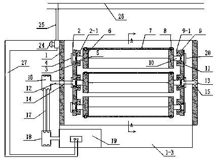
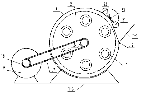
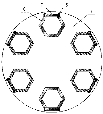
[0036] combine Figure 1 to Figure 19 A shot blasting machine for removing metal edges and corners according to the present invention will be further described.

[0037] In a preferred embodiment of a shot blasting machine for removing metal edges and corners according to the present invention, its structure consists of: bracket 1, safety door 1-1, hinge 1-2, base 1-3, left turntable 2, left bearing Seat 2-1, first convex through hole 2-2, left bearing 3, left plug 4, left short shaft 5, hexagonal hopper 6, feed port 6-1, bolt hole 6-2, hopper cover 7. Bolt 8, right turntable 9, right bearing seat 9-1, second convex through hole 9-2, right short shaft 10, right bearing 11, left connecting shaft 12, right connecting shaft 13, bracket left bearing 14 , bracket right bearing 15, driven pulley 16, transmission belt 17, driving pulley 18, motor 19, right block 20, pressure hammer 21, flip fixing block 22, rotating shaft 23, switch 24, lower live wire 25, external power supply Lin...


PUM


Abstract

The invention aims to provide a shot blasting machine for removing metal edges and corners. The shot blasting machine for removing the metal edges and corners structurally comprises a support, a safety door, a hinge, a base, a left rotary plate, a left bearing pedestal, a first convex through hole, a left bearing, a left plug, a left short shaft, a hexagonal hopper, a feeding inlet, a bolt hole, ahopper cover, a bolt, a right rotary plate, a right bearing pedestal, a second convex through hole, a right short shaft, a right bearing, a left connection shaft, a right connection shaft, a supportleft bearing, a support right bearing, a driven belt pulley, a transmission belt, a driving belt pulley, a motor, a right plug, a pressure hammer, a turnover fixing block, a rotary shaft, a switch, alower firing line, an external power line and an inner wire. The support and the base are connected in a welded mode; the support left bearing and the support right bearing are arranged at the centersof the two ends of the support separately; and the middle of the left connection shaft is installed in an inner hole of the support left bearing, and the right end of the right connection shaft is installed in an inner hole of the support right bearing.

Description

【Technical field】 [0001] The invention belongs to the technical field of shot blasting equipment, and in particular relates to a shot blasting machine for removing metal edges and corners. 【Background technique】 [0002] At present, for some metal semi-finished products with edges, corners, edges, burrs, and top cones that affect the production of the next process, sand grinding, grinding wheel grinding, wire brushing, sandblasting, etc. For some products with high precision requirements, the roughness of the product surface cannot be controlled by the above methods, and the product is often scrapped, resulting in high production costs for a single product. One of the reasons for the high price of this type of product is that the dust cannot be effectively controlled when the above-mentioned method is used, which will damage the environment of the production site and cause harm to the physical and mental health of the production workers. Therefore, a method of removing The ...

Claims


Application Information

Patent Timeline
IPC IPC(8): B24B31/033B24B31/12
CPCB24B31/033B24B31/12
Inventor 高飞
Owner 高飞
Why Eureka
Try Eureka