
3D printing method suitable for cylindrical parts

A 3D printing and 3D printer technology, applied in the field of 3D printing, can solve the problems of curve contour distortion, large vibration of printing head, affecting printing accuracy and printing speed, etc., and achieve the effect of increasing printing speed, increasing strength and improving printing accuracy

Active Publication Date: 2019-01-11
CHENGDU UNIVERSITY OF TECHNOLOGY
View PDF2 Cites 6 Cited by
  • Summary
  • Abstract
  • Description
  • Claims
  • Application Information

AI Technical Summary

Problems solved by technology

[0004] The purpose of the present invention is to solve the technical problems that when printing a three-dimensional model with a curved profile in the existing 3D printing method, the curved profile is distorted, and the frequent acceleration and deceleration of the printing head will cause large vibrations, which will affect the printing accuracy and printing speed.

Method used


Image

  • 3D printing method suitable for cylindrical parts
  • 3D printing method suitable for cylindrical parts
  • 3D printing method suitable for cylindrical parts

Examples


Embodiment Construction

[0025] The preferred embodiments of the present invention will be described below in conjunction with the accompanying drawings. It should be understood that the preferred embodiments described here are only used to illustrate and explain the present invention, and are not intended to limit the present invention.

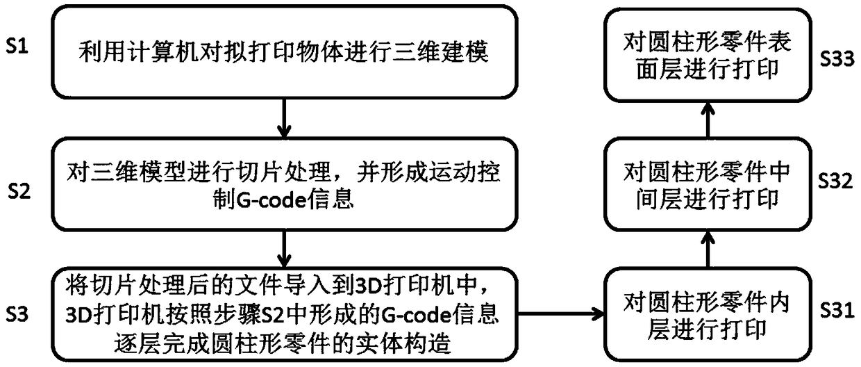
[0026] Such as figure 1 As shown, the present invention provides a kind of 3D printing method that is suitable for cylindrical part, and this method comprises the following steps:

[0027] Step S1: use computer design software to carry out three-dimensional modeling of the cylindrical part to be printed.

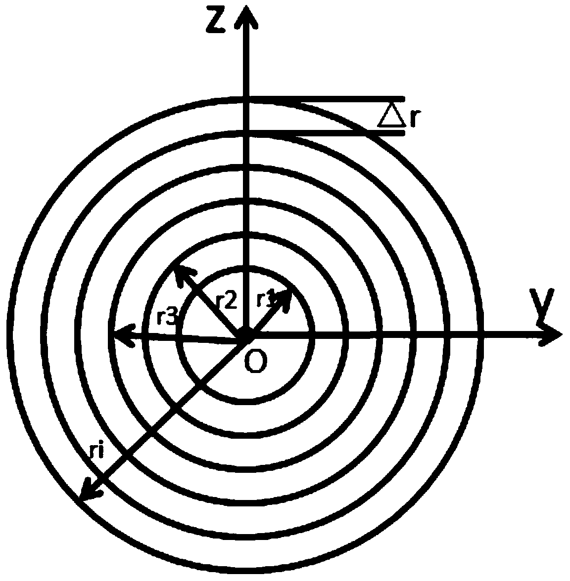
[0028] Step S2: Perform slice processing on the 3D model, and form motion control G-code information. The specific operation of slicing the 3D model is as follows: figure 2 As shown, along the central axis of the cylindrical part, use the cylindrical surface to slice the cylindrical part, and divide the cylindrical part into several layers with a thickness that...


PUM


Abstract

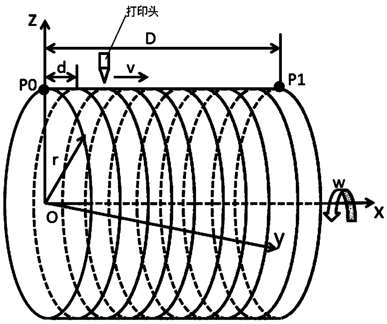
The invention discloses a 3D printing method suitable for cylindrical parts. The 3D printing method suitable for the cylindrical parts comprises the following steps that S1, the to-be-printed cylindrical parts are subjected to three-dimensional modeling through computer design software; S2, a three-dimensional model is subjected to slicing processing through a slicing method of cylindrical face pieces, and movement control G-code information is formed; and S3, files subjected to slicing processing enter a 3D printer, the 3D printer finishes solid construction of the cylindrical parts layer bylayer from inside to outside according to the G-code information formed in the step 2, the 3D printer adopts a printing tube arranged in the X direction as a printed piece adhesion platform, the printing tube can rotate along the central axis, and a printing head is arranged over the printing tube and can horizontally move in the length direction of the printing tube and move vertically in the Z direction. The 3D printing method suitable for the cylindrical parts avoids shape distortion caused when a straight line replaces a curved line during slicing of the parts with curved section profiles.

Description

technical field [0001] The invention belongs to the technical field of 3D printing, and in particular relates to a 3D printing method suitable for cylindrical parts. Background technique [0002] 3D printing technology is a technology that uses the method of gradually accumulating materials to construct solid parts. It is called a manufacturing technology with industrial revolution significance. With the advantages of high efficiency, short manufacturing cycle, and low cost, it is widely used in product development and production processes in the fields of automobiles, aerospace, and industrial design. [0003] Slicing is one of the most important processes for 3D printers to complete parts from model to entity. The 3D model is layered and sliced ​​through slicing software, and path files are generated to control the movement of the print head, extrusion mechanism and printing platform. The existing 3D printing slicing method is to use enough triangular faces in a certain d...

Claims


Application Information

Patent Timeline
Patent Type & Authority Applications(China)
IPC IPC(8): B29C64/386B33Y50/00
CPCB33Y50/00B29C64/386
Inventor 任涛张印李雨佳涂庆
Owner CHENGDU UNIVERSITY OF TECHNOLOGY
Learn More