
Vertical oven for circuit board and drying method thereof

A circuit board and vertical technology, applied in the field of circuit board drying equipment, can solve the problems of large occupied area and poor drying effect

Active Publication Date: 2019-01-11
QUZHOU CHUANTE ELECTRONICS TECH CO LTD
View PDF11 Cites 9 Cited by
  • Summary
  • Abstract
  • Description
  • Claims
  • Application Information

AI Technical Summary

Problems solved by technology

[0005] In view of the deficiencies in the prior art, the purpose of the present invention is to provide a vertical oven for circuit boards and its drying method, aiming to solve the defects of large occupied area and poor drying effect in the above-mentioned background technology

Method used


Image

  • Vertical oven for circuit board and drying method thereof
  • Vertical oven for circuit board and drying method thereof
  • Vertical oven for circuit board and drying method thereof

Examples


Embodiment 1

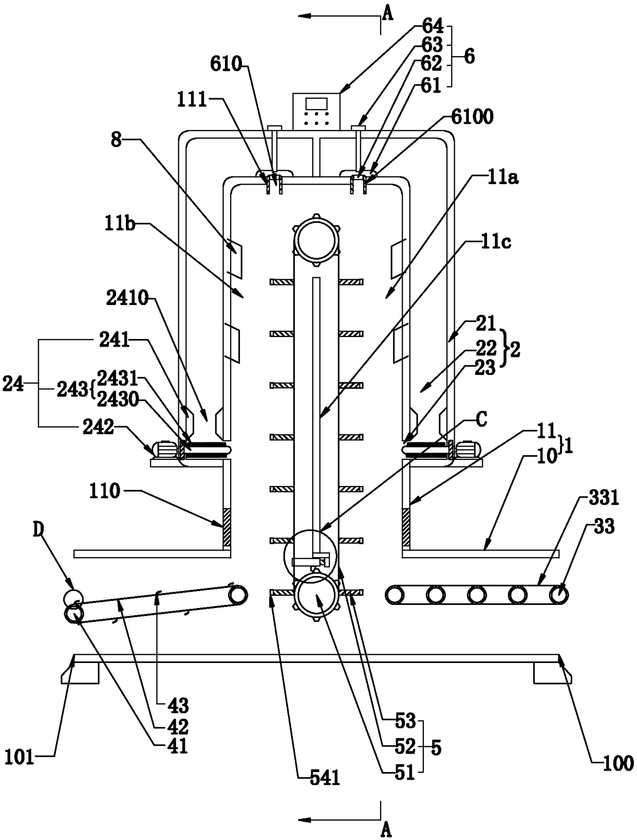
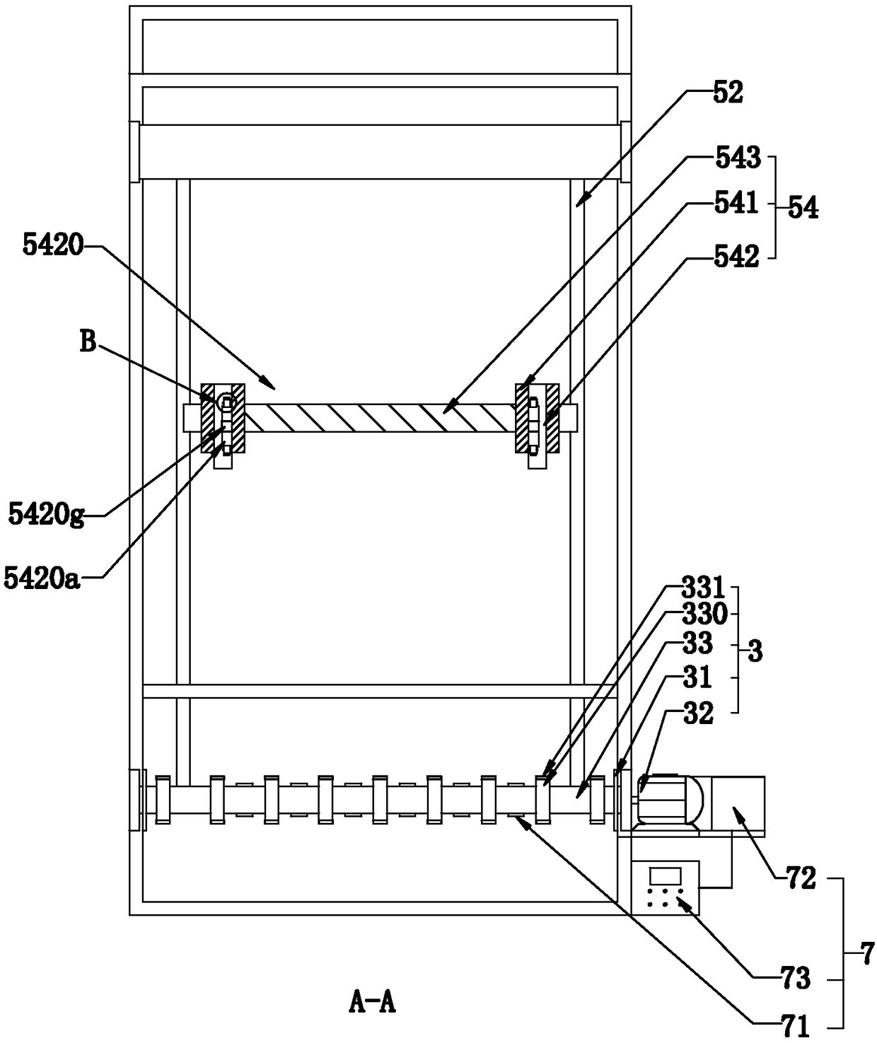
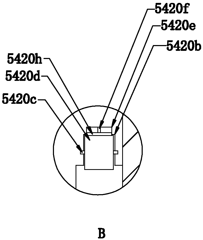
[0034] Such as Figure 1 to Figure 7 As shown, the present invention discloses a vertical oven for circuit boards. In a specific embodiment of the present invention, it includes a main box body 10 and a heating box body 11 vertically connected to the middle part of the top end surface of the main box body 10. The vertical box body 1 in the shape of "丄", the heat preservation assembly 2 arranged on the outer wall of the heating box body 11, the inlet 100 and the outlet 101 respectively arranged at both ends of the main box body 10, and the inlet 100 and the outlet 101 respectively The input assembly 3 and the output assembly 4 used to transport the circuit board are located inside the heating box 11 and are used to transport the circuit board frame on the input assembly 3 to the top of the heating box 11 for one week and then The lifting assembly 5 that transports the circuit board frame to the output assembly 4; the outer walls on both sides of the intersection between the hea...

Embodiment 2

[0047] A method for drying a circuit board in a vertical oven, characterized in that it comprises the following steps:

[0048] S1: Place the circuit board frame with the circuit board on the input assembly located at the entrance of the main box, and transport it to the inside of the heating box through the input assembly;

[0049] S2: The lifting component receives the circuit board frame on the input component through the clamping device and transports the received circuit board frame to the top of the heating box. After passing the top of the heating box, the circuit board frame is placed on the main box delivery of output components at the outlet of the body;

[0050] S3: When the clamping device holding the circuit board frame moves to the output assembly, the part of the circuit board can be separated from the clamping device by pushing the component, and the part of the circuit board can be pushed to the output assembly;

[0051] S4: The heated circuit board frame is ...


PUM


Abstract

The invention relates to a vertical oven for a circuit board and a drying method thereof. The vertical oven for the circuit board is characterized by comprising a vertical box body composed of a mainbox body and a heating box body, an insulating component arranged on the outer wall of the heating box body, and an inlet and an outlet respectively arranged in both ends of the main box body, an input assembly and an output assembly respectively arranged at the inlet and the outlet for transporting the circuit board, and a lifting assembly arranged inside the heating box body and used for transporting a circuit board frame on the input assembly to the top of the heating box body for one circle and transporting the circuit board frame to the output assembly; air inlets for supplying heat to the interior of the heating box body are arranged in the outer walls of the both sides of the junction of the heating box body and the main box body respectively, air outlets for discharging the hot airinside the heating box body into the interior of the insulating component are arranged at the top of the heating box body at intervals, and a control component is arranged at each air outlet. The vertical oven for the circuit board has the beneficial effect that the problem that the equipment occupies too much space can be solved, and the baking effect on the circuit board can be ensured.

Description

technical field [0001] The invention relates to the technical field of drying equipment for circuit boards, in particular to a vertical oven for circuit boards and a drying method thereof. Background technique [0002] Circuit board, also known as circuit board, refers to a highly reliable and excellent flexible printed circuit board made of materials such as polyimide or polyester film. It has the characteristics of high wiring density, light weight, thin thickness and good bendability. There are many types of circuit boards on the market, generally ceramic circuit boards, alumina ceramic circuit boards, aluminum nitride ceramic circuit boards, circuit boards, PCB boards, aluminum substrates, high-frequency boards, thick copper boards, impedance boards, PCBs, Ultra-thin circuit boards, ultra-thin circuit boards, printed (copper etching technology) circuit boards, etc. The circuit board makes the circuit miniaturized and intuitive, and plays an important role in mass produ...

Claims


Application Information

Patent Timeline
IPC IPC(8): F26B15/22F26B25/00F26B25/02F26B25/18
CPCF26B15/22F26B25/004F26B25/02F26B25/185Y02P70/10
Inventor 兰胜有
Owner QUZHOU CHUANTE ELECTRONICS TECH CO LTD
Learn More