
System and method for measuring parallel multi-line laser based on homography matrix

A homography matrix, measurement system technology, applied in measurement devices, optical devices, instruments, etc., can solve problems such as laser line matching ambiguity, and achieve the effects of high accuracy, strong stability and fast efficiency

Pending Publication Date: 2019-01-11
NANJING UNIV OF AERONAUTICS & ASTRONAUTICS
View PDF0 Cites 17 Cited by
  • Summary
  • Abstract
  • Description
  • Claims
  • Application Information

AI Technical Summary

Problems solved by technology

[0004] In order to solve the problem of laser line matching ambiguity in the process of multi-line laser scanning measurement, the present invention provides a parallel multi-line laser measurement method based on homography matrix, which can effectively calculate the matching laser line of the laser line to be matched, According to the principle of binocular parallax, the laser line is reconstructed in 3D

Method used


Image

  • System and method for measuring parallel multi-line laser based on homography matrix
  • System and method for measuring parallel multi-line laser based on homography matrix
  • System and method for measuring parallel multi-line laser based on homography matrix

Examples


Embodiment 1

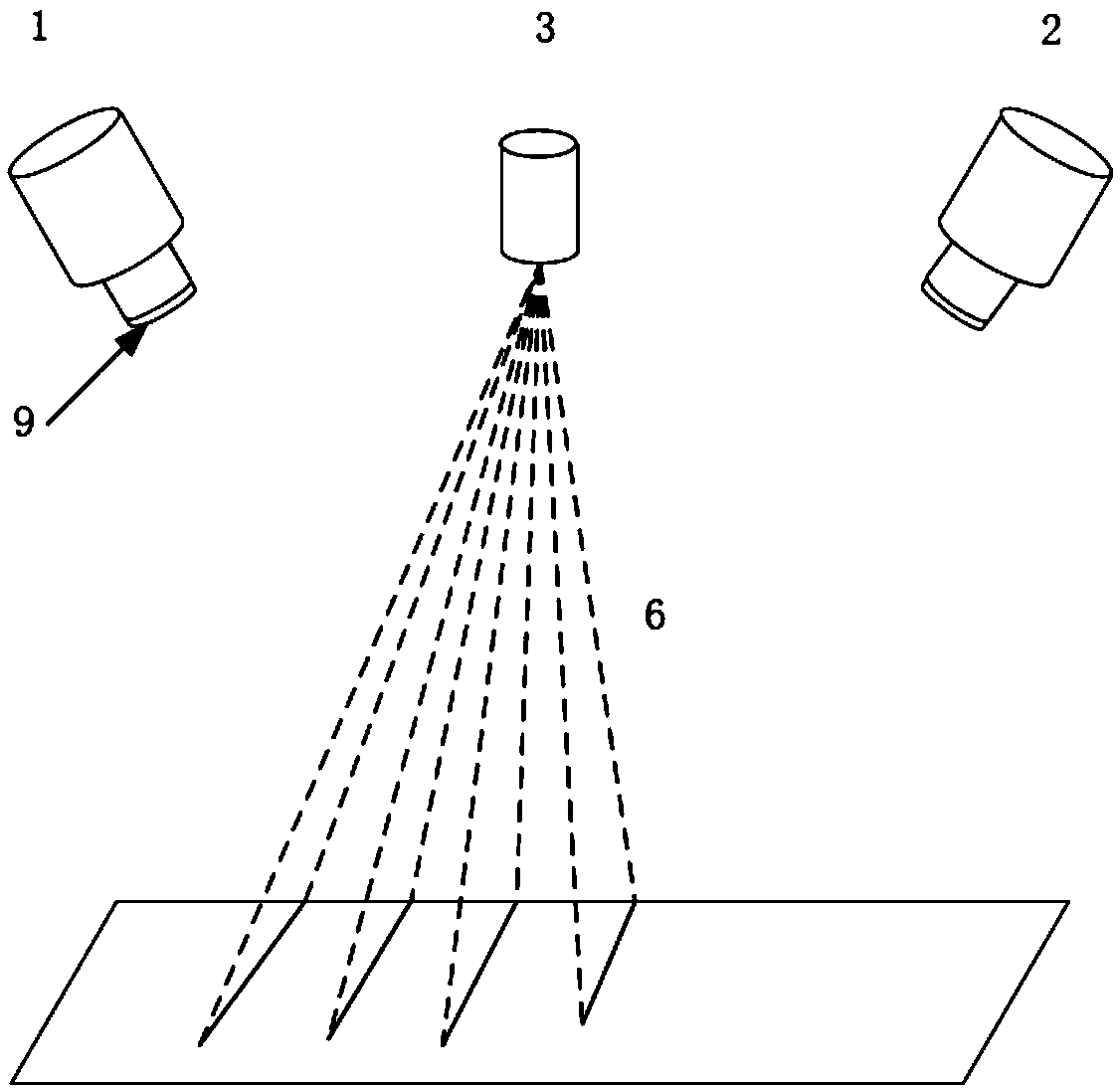
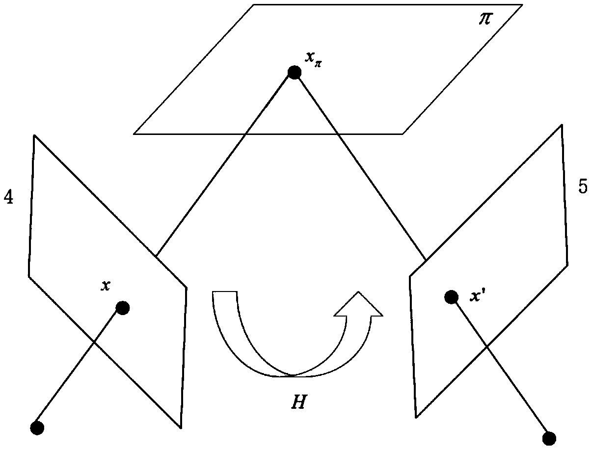
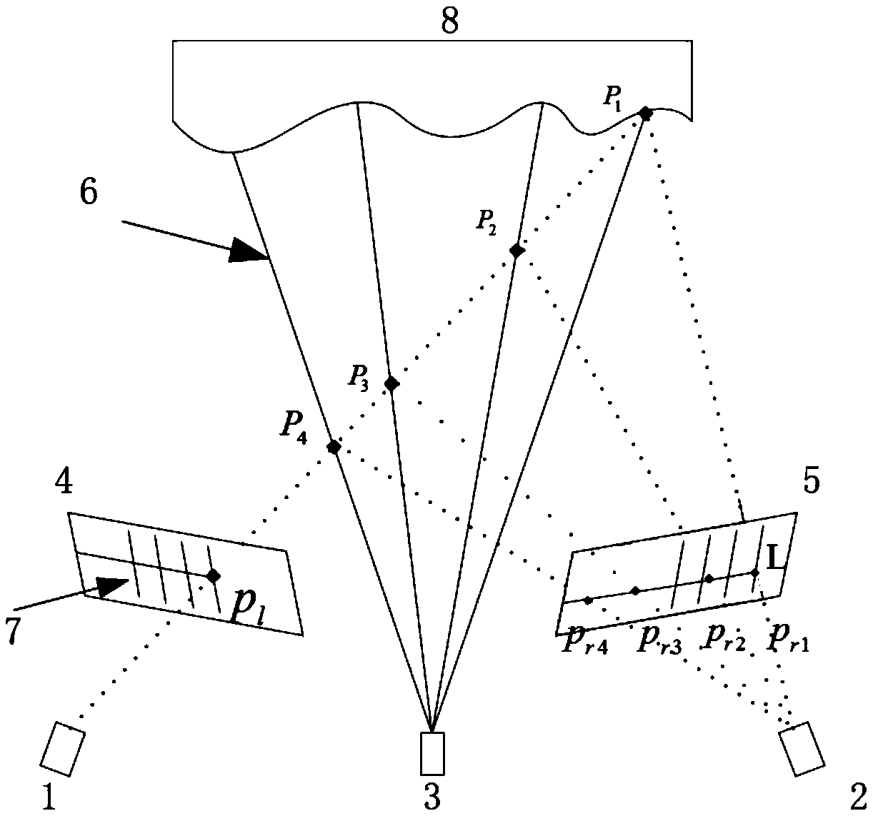
[0039] First, the parallel multi-line laser three-dimensional scanning system in the present invention is described, as figure 1 As shown, the measurement system is made up of two industrial cameras 1, 2, a laser projector 3 and two camera filters 9, and the laser projector 3 projects a plurality of parallel laser lines. For example, the number of the parallel laser lines is not limited to 4, and intersects with the object to be measured to form a modulated light strip. The light strip is located on the light plane in space, and is imaged on the camera CCD through perspective projection. Compared with the traditional structured light measurement system, this paper does not need to calibrate the light plane equation on the light plane 6, but only needs to use the laser plane 6 to induce the homography matrix between the left and right image planes, so the calibration between the left and right image planes The homography matrix of is the key to building a 3D measurement model.

...


PUM


Abstract

The invention provides a system and method for measuring parallel multi-line lasers based on a homography matrix. The method mainly comprises the following steps of: calibrating a camera system through a planar target to obtain internal and external parameters of the camera; calibrating the laser measuring system through a stereoscopic target, and inducing the homography relation between the leftand the right image planes of a binocular camera through the laser plane to obtain the calibration parameters of the laser system due to the relatively fixed characteristics of the laser plane and theplane positions of the left and the right cameras; mapping the laser lines to be matched of the left image to the right image to obtain a plurality of mapped laser lines through the calibration parameters of the laser measuring system; by calculating the coincidence degree of the mapped laser lines, taking a mapped laser line corresponding to the maximum coincidence degree as a laser line corresponding to the laser line to be matched so as to realize the correct matching of the laser lines in the left and the right images; and according to the correctly matched laser lines, reconstructing thethree-dimensional data of the laser lines to obtain the three-dimensional information of an object surface through the principle of the binocular stereovision measurement.

Description

technical field [0001] The invention relates to the technical field of laser three-dimensional measurement, in particular to a parallel multi-line laser measurement method based on a homography matrix. Background technique [0002] Structured light 3D visual measurement technology is the most commonly used modern technology in the field of 3D digitization. It overcomes the limitations of traditional measuring instruments with its advantages of non-contact, fast scanning speed, large amount of information, high precision, and strong real-time performance. , and become an important means to directly obtain high-precision 3D data of the target. It greatly reduces measurement costs, saves time, is easy to use, and has a wide range of applications. It has great room for development in engineering measurement, deformation monitoring, cultural relics protection, forestry and agriculture, medical research, and battlefield simulation. [0003] Currently commonly used laser modes are...

Claims


Application Information

Patent Timeline
IPC IPC(8): G01B11/24
CPCG01B11/2433
Inventor 崔海华田威李想程筱胜廖文和
Owner NANJING UNIV OF AERONAUTICS & ASTRONAUTICS
Learn More