
Spatiotemporal measurement device for ultrafast laser fields

A measurement device, ultrafast laser technology, applied in the direction of instruments, etc., can solve the problems of loss of time information, loss of spatial resolution of optical information, difficulty in achieving high experimental accuracy, etc.

Pending Publication Date: 2019-01-11
EAST CHINA NORMAL UNIV
View PDF4 Cites 12 Cited by
  • Summary
  • Abstract
  • Description
  • Claims
  • Application Information

AI Technical Summary

Problems solved by technology

[0005] The usual technology is to obtain the distribution law of the space domain by integrating the time domain, or to obtain the evolution law of the time domain by integrating the space domain. Time-to-time optical information loses spatial resolution
In some cases where space-time distortion exists, it is difficult to achieve high experimental accuracy

Method used


Image

  • Spatiotemporal measurement device for ultrafast laser fields
  • Spatiotemporal measurement device for ultrafast laser fields
  • Spatiotemporal measurement device for ultrafast laser fields

Examples


Embodiment 1

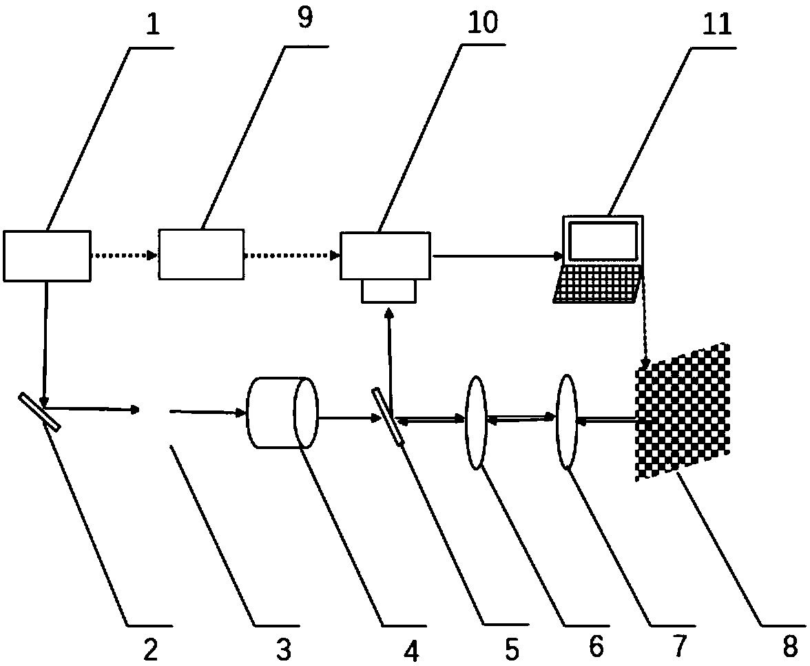
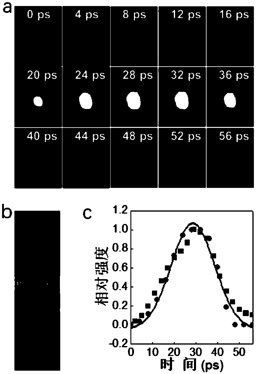
[0050] refer to Figure 1-2 , figure 2 is the spatiotemporal measurement diagram of the laser field with a center wavelength at 800 nm.

[0051] The laser field 1 to be measured passes through the high mirror 2, the thin paper screen 3, the objective lens 4, and then through the cube beam splitter 5, enters the first convex lens 6, the second convex lens 7, and reaches the digital micromirror device (DMD) 8. The light reflected by the two-convex lens 7 enters the streak camera 10 after reaching the cube beam splitter 5 again;

[0052] The computer 11 is electrically connected to the digital micromirror device 8 and the streak camera 10 respectively, and the digital delay generator 9 is electrically connected to the streak camera 10 and the laser field 1 to be measured respectively.

[0053] The laser field 1 is coded by the digital micromirror device 8 and then reaches the streak camera 10. The streak camera 10 deflects and superimposes it to obtain a forward compressed ima...

Embodiment 2

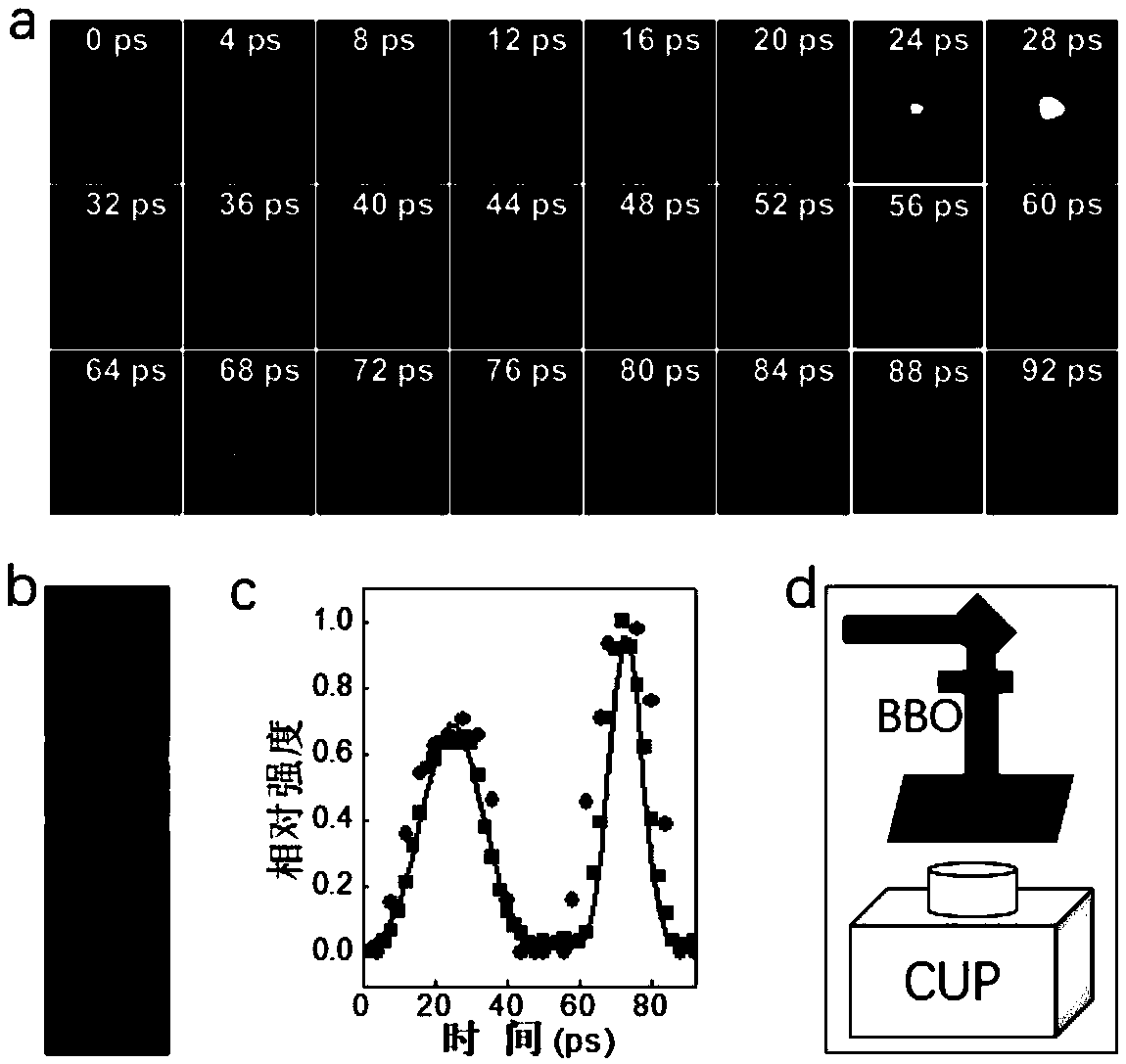
[0058] refer to figure 1 , image 3 , image 3 It is the spatio-temporal measurement map of the two-color field laser pulse field.

[0059] in: image 3 d is the experimental condition, the difference is that a piece of BBO crystal is placed in the original optical path, and then a two-color pulse of 400nm and 800nm ​​is generated. Due to effects such as dispersion, the two pulses will have a certain time delay.

[0060] image 3 a is the reconstruction result. Each picture represents the spatial information of the laser field at a certain moment, mainly including the light field distribution on the cross section of the laser field. The reconstruction results will show the process of the two laser fields changing from weak to strong and then weak again. The time scale of the two pulses and the spatial distribution within this time scale are recorded.

[0061] image 3 b is the acquisition number of streak camera in one-dimensional working state.

[0062] image 3 c is...

Embodiment 3

[0064] refer to figure 1 , Figure 4 , Figure 4 It is the spatiotemporal measurement map of supercontinuum laser pulse field.

[0065] in: Figure 4 d is the experimental conditions, the difference is that a convex lens is placed in the original light path to focus the light, and the supercontinuum of water is generated in the cuvette filled with water, and then the supercontinuum is irradiated on the paper screen.

[0066] Figure 4 a is the reconstruction result. On the premise of recording the evolution of the entire spot, it can also be found that the pulse width has been broadened to a certain extent.

[0067] Figure 4 b is the collected data in one-dimensional working state.

[0068] Figure 4 c is the Gaussian fitting of the one-dimensional and two-dimensional results, where the small squares represent one-dimensional data, and the small dots represent two-dimensional data. Similarly, the Gaussian fitting results of the two are very similar. Here, the spatiot...


PUM


Abstract

The invention discloses a spatiotemporal measurement device for ultrafast laser fields, including an imaging system, a synchronization system, and a data acquisition and processing system. The invention combines the advantages of a stripe camera and a compressed sensing theory in two-dimensional compression imaging, forms dynamic scenes of the captured two-dimensional laser fields by directly illuminating the spots of the laser fields on a paper screen, and reconstructs the obtained compressed data by a second iterative threshold compression algorithm to finally realize the spatiotemporal measurement of any laser field. In the invention, the laser fields to be measured enters a convex lens orderly through a high-reflection mirror, a thin paper screen, an objective lens, and a cube beam splitter, and then reaches a digital micro-mirror device; the reflected light enters the stripe camera after reaching the cube beam splitter again; and a computer controls the collection of image information and post-processing of data. The spatiotemporal measurement device provided by the invention has an entire measurement process as an ultra-fast process of single measurement, with no reference light needed in the measurement, and has the characteristics of simple optical path, fast operation speed of the algorithm, and wide coverage band.

Description

technical field [0001] The invention relates to the technical field of laser field measurement, which is used for simultaneous measurement of time and space information of a pulsed laser field, in particular to a space-time measurement device for an ultrafast laser field. Background technique [0002] It is a continuous development process for people to understand laser deeply and then to use it. Today, ultrashort pulse lasers have been widely used in scientific research in the fields of ultrafast phenomenon research, precision material processing, ultraprecision surgery, optical communication, and high-tech design. Laser parameters are an important measure of laser technology, and their measurement is a research direction of great significance, as well as a basic work in the research, production and application of lasers. [0003] The analysis of laser characteristics in the prior art includes its distribution characteristics in time, space and frequency spectrum, which ar...

Claims


Application Information

Patent Timeline
Patent Type & Authority Applications(China)
IPC IPC(8): G01J11/00
CPCG01J11/00
Inventor 曹烽燕杨承帅齐大龙何一林杨岩孙真荣张诗按
Owner EAST CHINA NORMAL UNIV
Learn More