Clamping device suitable for testing shear property of fiber reinforcement bodies and prepregs thereof

A fiber reinforcement and prepreg technology, which is applied in the direction of using a stable shear force to test the strength, strength characteristics, measuring devices, etc. Structural stability, testing the effect of shear deformation and large-angle shear deformation

Inactive Publication Date: 2019-01-11
HUAZHONG UNIV OF SCI & TECH
View PDF7 Cites 2 Cited by
  • Summary
  • Abstract
  • Description
  • Claims
  • Application Information

AI Technical Summary

Problems solved by technology

[0004] In view of the above defects or improvement needs of the prior art, the present invention provides a fixture suitable for testing the shear performance of fiber reinforced bodies and their prepregs, through the structure of the main frame, clamping unit and tensile loading unit of key components The purpose of the design and position layout is to make the object to be clamped be clamped while

Method used


Image

  • Clamping device suitable for testing shear property of fiber reinforcement bodies and prepregs thereof
  • Clamping device suitable for testing shear property of fiber reinforcement bodies and prepregs thereof
  • Clamping device suitable for testing shear property of fiber reinforcement bodies and prepregs thereof

Examples


Example Embodiment

[0044] Example 1:

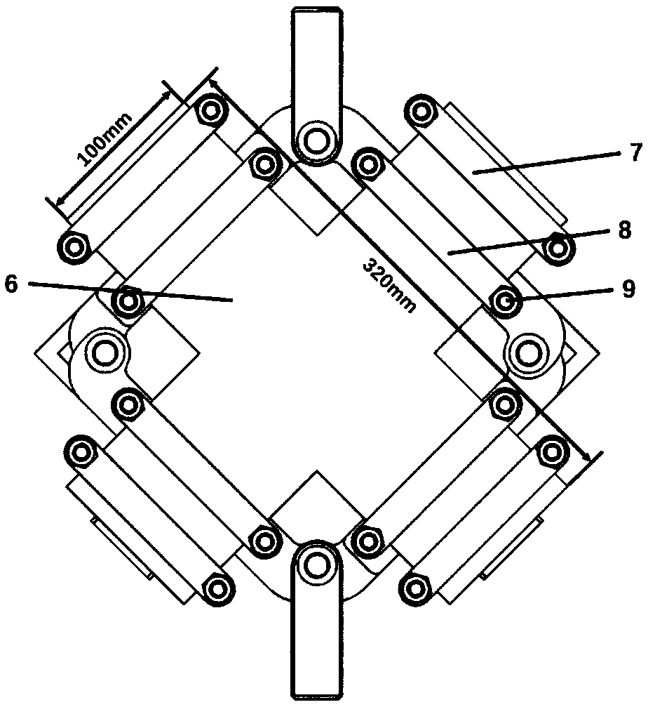
[0045] Step 1: Prepare the test sample, cut the T300 plain weave carbon fiber cloth to be tested to the specified shape, with a long side of 320mm and a short side of 100mm in a cross-shaped pattern. The warp and weft yarn directions of the fiber cloth are consistent with the cross direction.

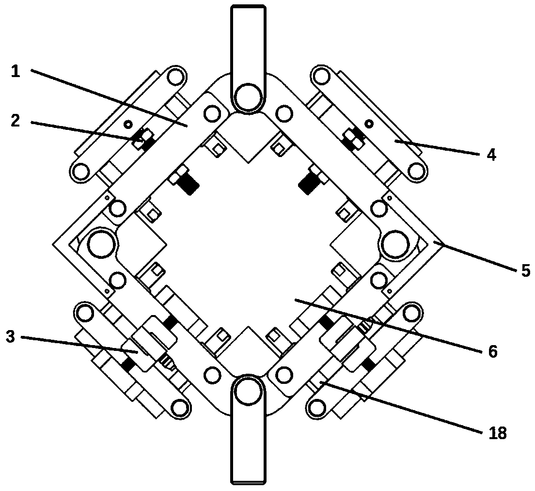
[0046] Step 2: Install the main frame on the tensile testing machine and install the tension and compression sensor 3 on the main frame and power on.

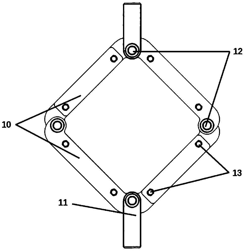
[0047] Step 3: Adjust the chuck stroke of the tensile testing machine and cooperate with the L-shaped limit rod to make the initial frame maintain a square shape, that is, the main frame connecting rods are at 90° to each other. Place the edge of the cross-shaped pattern between the rubber pads 17 of the rear clamping portion, and lock the bolts on the rear clamping portion 8 so that the upper clamping plate 16 and the lower clamping plate 15 clamp the pattern and fix them on the movable base 14 on.

[0048] Step 4: Adjust t...

Example Embodiment

[0051] Example 2:

[0052] Step 1: Prepare the test sample, and cut the carbon fiber reinforced polyether ether ketone prepreg to be tested into a cross-shaped pattern with a long side of 320mm and a short side of 100mm. The direction of the warp and weft yarns of the fiber cloth is consistent with the cross direction. Among them, the carbon fiber reinforced polyether ether ketone prepreg is a prepreg prepared by electrostatic powder spraying, the reinforcement is preferably T300 plain weave carbon fiber cloth, and the matrix is ​​preferably Vicote 702 polyether ether ketone fine powder from Shanghai Victrex Company, and Mix 2-3% volume fraction of PTFE powder.

[0053] Step 2: Install the main frame on the tensile testing machine, install the tension and compression sensor 3 on the main frame and power on.

[0054] Step 3: Adjust the chuck stroke of the tensile testing machine and cooperate with the L-shaped limit rod to make the main frame maintain a square shape, that is, the mai...


PUM


Abstract

The present invention belongs to the field of material property testing, and particularly relates to a clamping device suitable for testing the shear property of fiber reinforcement bodies and prepregs thereof. The clamping device comprises a main body frame, a clamping unit, a tensile force loading unit and a sensor, wherein the main body frame comprises four connecting rods, the four connectingrods are connected to form a square, the main body frame is provided with a connecting member for connecting to an external testing machine and a position limiting rod for limiting the angle of the connecting rod of a right angle, the clamping unit comprises a front clamping part and a rear clamping part, the front clamping part is used for pre-clamping and ensuring the parallel states respectively between the warp direction and the weft direction of a to-be-clamped object and the adjacent connecting rods, the rear clamping part further fixes the to-be-clamped object after the tensile force loading unit loads force, thee tensile force loading unit is used for respectively applying tensile force along the warp direction and the weft direction, and the sensor is used for detecting the loadedtensile force. With the clamping device of the present invention, the structure is stable, the measuring process is not slippery, and the large angle shear deformation can be tested.

Description

technical field [0001] The invention belongs to the field of material performance testing, and more specifically relates to a fixture suitable for testing the shearing performance of a fiber reinforced body and its prepreg. Background technique [0002] At present, braided fiber reinforced composites have been widely used in aerospace, national defense, automobile and wind power fields due to their advantages of high specific strength, high specific stiffness and strong designability. For the forming of braided fiber reinforced composites, whether it is the laying process of fiber preforms in resin transfer molding (RTM) molding of thermosetting resin matrix composites or the thermocompression molding process of thermoplastic resin matrix composites, braided fiber reinforced The shear performance of the body and its prepreg is one of the important molding factors that affect the quality of the final product. Domestic researchers of woven fiber composites usually use off-axis...

Claims


Application Information

Patent Timeline
IPC IPC(8): G01N3/04G01N3/24
CPCG01N3/04G01N3/24
Inventor 黄志高周华民邓天正雄张云王云明
Owner HUAZHONG UNIV OF SCI & TECH
Why Eureka
Try Eureka