
Eureka
For R&D, Eureka makes reading and utilizing patents & technical documents easy.
Eureka AIR
Designed for self-driven R&D workflows. Generate viable solutions, solve complex R&D challenges, empower your innovation with AI.

Eureka Materials
Designed for material experts only. Revolutionize your material R&D, from search, analyze, to developing new materials.

TechResearch
Generate reliable direction feasibility study reports for your R&D in just a few steps.

TechSeek
Discover and master advanced knowledge NOW. Basics, ideas, possibilities, all at once.

TechMind
As an expert in R&D Theories, TechMind can generates customized viable solutions instantly.

TechRisk
Analyze your overall solution with one click, know your potential R&D risks in advance.

TechMonitor
Get weekly tech updates, stay abreast of the latest tech innovations and key insights.
Ion implanter and ion beam control method
A control method and ion beam technology, which is applied in the direction of discharge tubes, electrical components, circuits, etc., can solve the problems of low ion implantation productivity and inability to control the ion beam throughput, so as to reduce costs, improve linearity and energy uniformity, Drive flexible and precise effects
- Summary
- Abstract
- Description
- Claims
- Application Information
AI Technical Summary
Problems solved by technology
Method used
Image

Examples
Embodiment approach 1
[0046] The first embodiment of the present invention provides a method for controlling ion beams. It is not necessary to reset the machine parameters in each process, and it can flexibly adapt to different processes by controlling the rotation angle of the beam stopper 2 in different processes. Changes in the process, increase production capacity, and reduce costs.
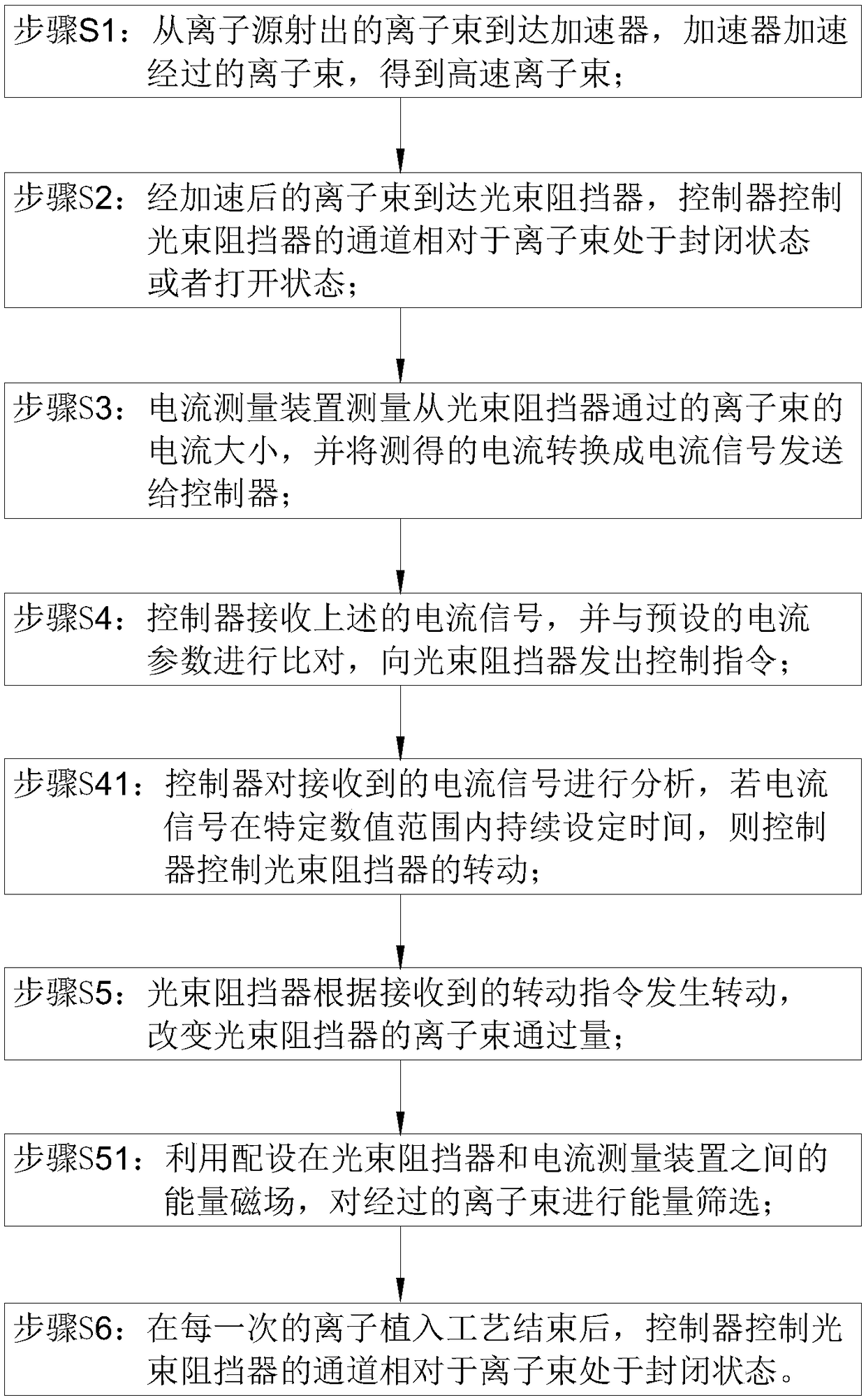
[0047] Specifically, see Figure 1-Figure 4 As shown, the control method of the ion beam includes the following steps:
[0048] Step S1: The ion beam emitted from the ion source 1 reaches the accelerator 3, and the accelerator 3 accelerates the passing ion beam to obtain a high-speed ion beam;
[0049] Step S2: The accelerated ion beam reaches the beam blocker 2, and the controller 100 controls the channel 6 of the beam blocker 2 to be in a closed state or an open state relative to the ion beam;
[0050] Step S3: the current measuring device 4 measures the current of the ion beam passing through the beam blocker...
Embodiment approach 2
[0069] The second embodiment of the present invention provides an ion implanter. By using the ion implanter in the second embodiment, it is not necessary to reset the machine parameters in each process. By controlling the beam blocker 2 in different processes The rotation angle in the middle can flexibly adapt to the changes of different processes, increase production capacity and reduce costs.
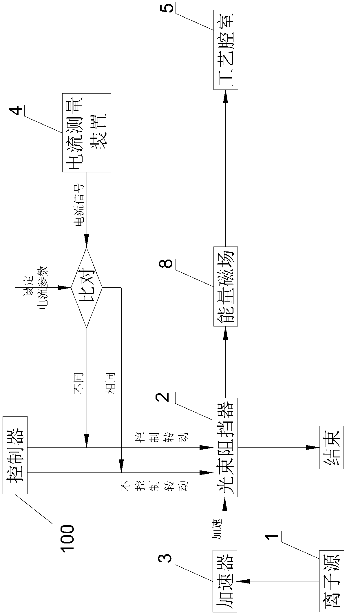
[0070] combine image 3 and Figure 4 From the point of view, the ion implanter of the present invention includes a controller 100, an ion source 1, a beam blocker 2, an accelerator 3 and a current measuring device 4, and the ion source 1, the beam blocker 2, the accelerator 3 and the current measuring device 4 are all Communicatively connected with the controller 100. In this embodiment, the ion source 1 , the accelerator 3 , the beam stopper 2 , the current measuring device 4 and the process chamber 5 are arranged in the order of ion beam flow.
[0071] The current measurement de...
Embodiment approach 3
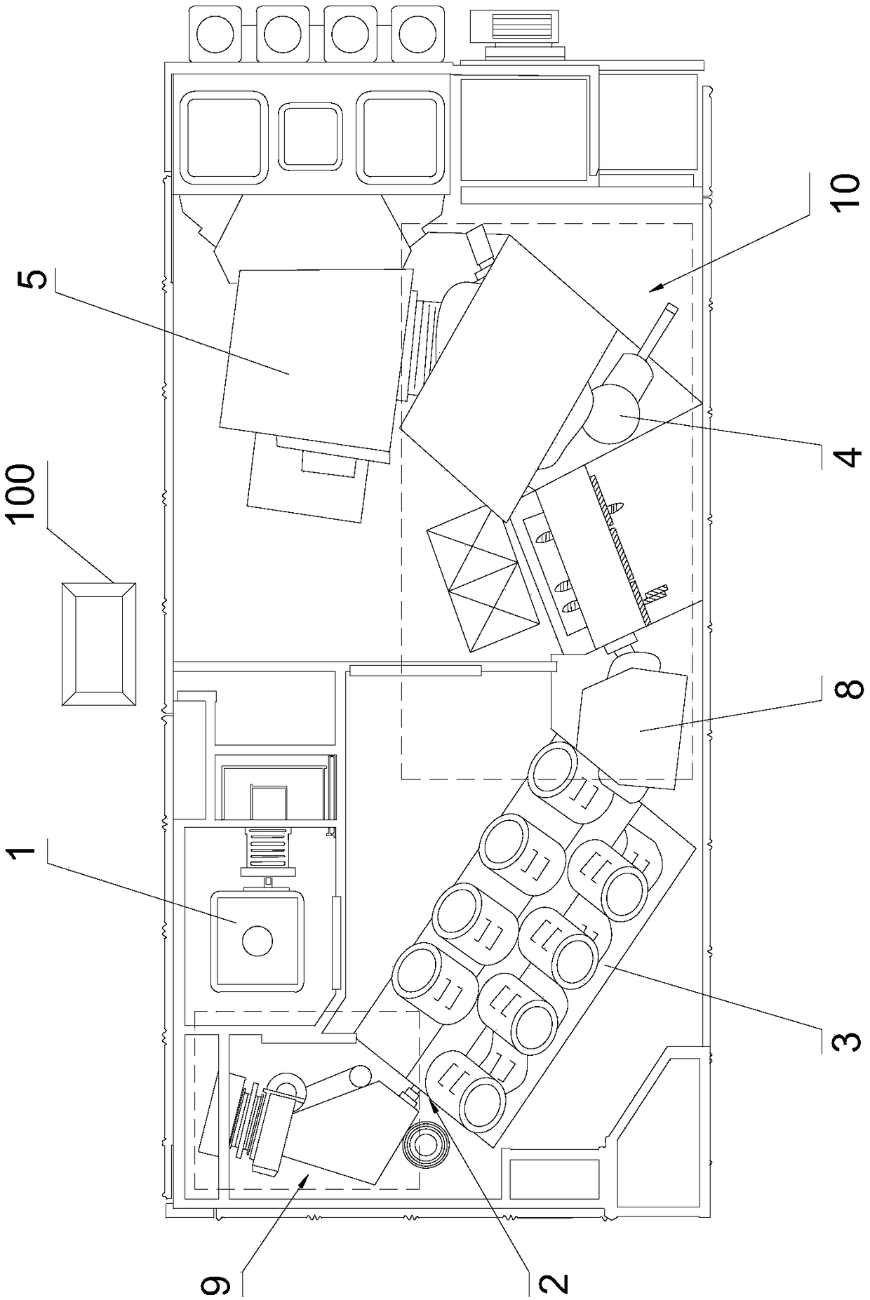
[0085] The third embodiment of the present invention provides an ion implanter, the third embodiment is a further improvement on the second embodiment, the main improvement is that in the third embodiment of the present invention, combined Figure 6 It can be seen that the area between the ion source 1 and the beam stopper 2 is formed as a low beam current conversion area 9, and the low beam current conversion area 9 can convert the direction of the passing ion beam. The area between the accelerator 3 and the process chamber 5 is formed as a high beam conversion region 10, which can convert the direction of the passing ion beam. Both the low beam current conversion area 9 and the high beam current conversion area 10 use a magnetic field to convert the direction of the ion beam.
[0086] There is also a homing module 11 in the controller 100. After each ion implantation process is finished, the homing module 11 of the controller 100 works so that the channel 6 of the beam stopp...
PUM
 Abstract
Description
Claims
Application Information
 - R&D Engineer
- R&D Manager
- IP Professional
- Industry Leading Data Capabilities
- Powerful AI technology
- Patent DNA Extraction
Browse by: Latest US Patents, China's latest patents, Technical Efficacy Thesaurus, Application Domain, Technology Topic, Popular Technical Reports.
© 2024 PatSnap. All rights reserved.Legal|Privacy policy|Modern Slavery Act Transparency Statement|Sitemap|About US| Contact US: help@patsnap.com