Cutting device for steel bar machining

A cutting device and steel bar processing technology, applied in the directions of cleaning methods and utensils, removing smoke and dust, chemical instruments and methods, etc., can solve the problem of not having the function of collecting iron filings, and achieve the effect of enhancing stability

Inactive Publication Date: 2019-01-15
河南永益同丰智能科技有限公司
View PDF5 Cites 9 Cited by
  • Summary
  • Abstract
  • Description
  • Claims
  • Application Information

AI Technical Summary

Problems solved by technology

[0004] The purpose of the present invention is to provide a cutting device for steel bar processing, which has the advantage of collecting iron filings and solves the problem that traditional cutting devices do not have the function of collecting iron filings

Method used


Image

  • Cutting device for steel bar machining
  • Cutting device for steel bar machining
  • Cutting device for steel bar machining

Examples


Embodiment Construction

[0017] The following will clearly and completely describe the technical solutions in the embodiments of the present invention with reference to the accompanying drawings in the embodiments of the present invention. Obviously, the described embodiments are only some, not all, embodiments of the present invention. Based on the embodiments of the present invention, all other embodiments obtained by persons of ordinary skill in the art without making creative efforts belong to the protection scope of the present invention.

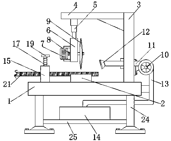
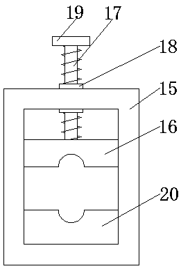
[0018] see Figure 1-3 , a cutting device for steel bar processing, comprising a base 1, the left side of the top of the base 1 is fixedly connected with a fixed frame 15, the bottom of the cavity of the fixed frame 15 is fixedly connected with a lower block 20, and the top of the cavity of the fixed frame 15 is slidably connected There is an upper block 16, the center of the top of the upper block 16 is vertically fixedly connected with a threaded rod 17, the...


PUM


Abstract

The invention discloses a cutting device for steel bar machining. The cutting device comprises a base. A workbench is fixedly connected to the center position of the top of the base. A fixing column is fixedly connected to the right side of the top of the base. A supporting plate is transversely and fixedly connected to the top of the left side of the fixing column. An electric telescopic rod is fixedly connected to the left side of the bottom of the supporting plate. A fixing base is fixedly connected to the bottom of the electric telescopic rod. A motor is arranged at the bottom of the leftside of the fixing base. Through cooperation of the workbench, the fixing column, the supporting plate, the electric telescopic rod, the fixing base, the motor, the rotation shaft, a cutting blade, anair suction pump, a communication pipe, a ventilation head, a connecting pipe and a collection box, iron scraps generated in the steel bar cutting process can be sucked in and collected, and the problem that a traditional cutting device does not have an iron scrap collecting function is solved; and a large number of iron scraps are prevented from being left after steel bar cutting, convenience isbrought to next cutting for users, and the cutting device is worthy of being used and popularized.

Description

technical field [0001] The invention relates to the technical field of steel bar processing, in particular to a cutting device for steel bar processing. Background technique [0002] Reinforcement processing is the production process of steel products for reinforced concrete projects or prestressed concrete projects. The production process of steel bars usually adopts flow operation. The process is as shown in the figure. After the stress steel bar processing and other processes are finished, it is transported to the construction site for installation. [0003] During building construction, in order to meet the requirements of the construction drawings, the user needs to cut the steel bars, so a cutting device is needed. However, the traditional cutting device does not have the function of collecting iron filings, and a large amount of broken iron will be splashed during the cutting process of the steel bars. Scraps and scraps of iron will cause damage to the face and body ...

Claims


Application Information

Patent Timeline
Patent Type & Authority Applications(China)
IPC IPC(8): B21F11/00B08B15/04
CPCB21F11/00B08B15/04
Inventor 张展悦
Owner 河南永益同丰智能科技有限公司
Why Eureka
Try Eureka