Flexible cooperative mechanical arm and control method thereof

A manipulator and manipulator technology, applied in the field of flexible collaborative manipulators and their control, can solve problems such as lack of low cost, and achieve the effect of improving collaboration and safety with people, avoiding damage, and avoiding damage.

Inactive Publication Date: 2019-01-15
南京秘塔网络科技有限公司
View PDF7 Cites 10 Cited by
  • Summary
  • Abstract
  • Description
  • Claims
  • Application Information

AI Technical Summary

Problems solved by technology

This type of demand does not require collaborative manipulators to meet industrial application standards, but there is still a lack of powerful low-cost products in this market

Method used


Image

  • Flexible cooperative mechanical arm and control method thereof
  • Flexible cooperative mechanical arm and control method thereof
  • Flexible cooperative mechanical arm and control method thereof

Examples


Embodiment 1

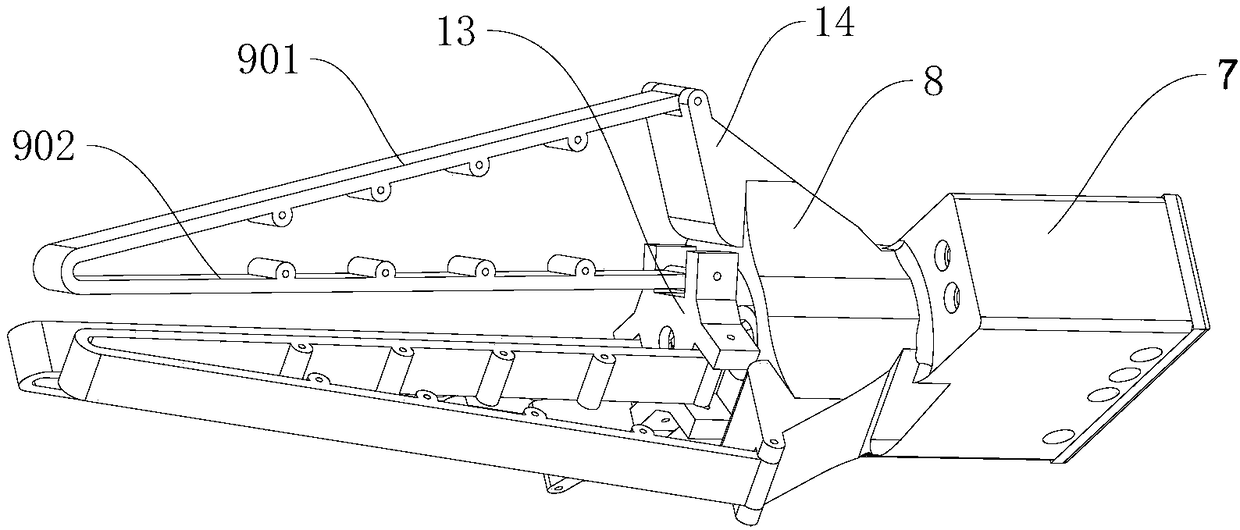
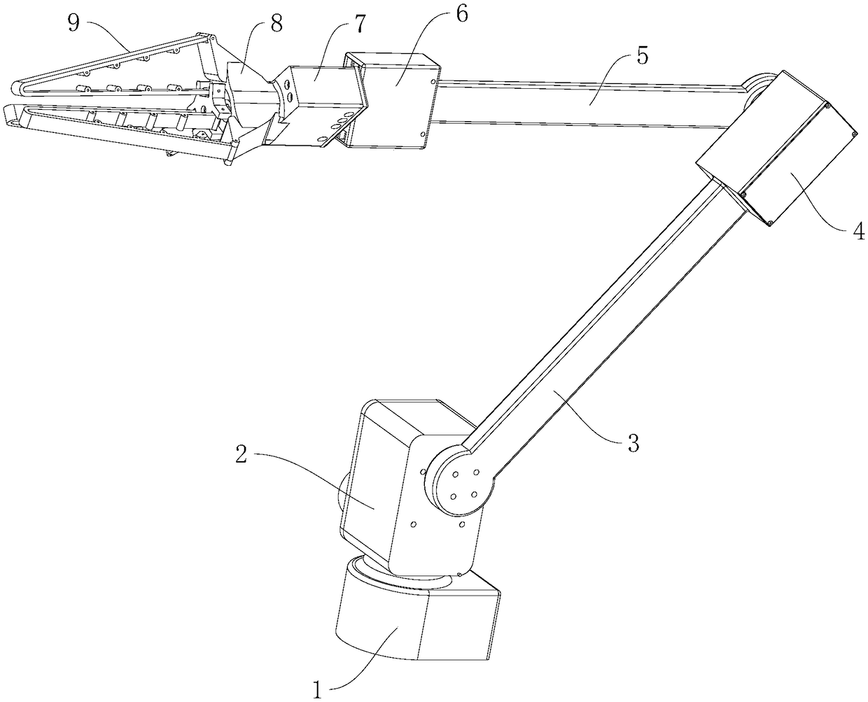
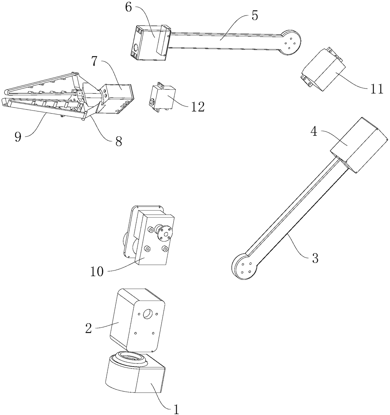
[0053] Such as figure 1 , figure 2 , image 3 As shown, this embodiment discloses a flexible cooperative robot arm, which includes a base 1, a main body of the robot arm, and an execution fixture. Specifically, the base is provided with a control panel and a bottom steering gear, and the bottom steering gear is used to drive the mechanical arm to rotate horizontally; the main body of the mechanical arm includes a first machine arm 3 and a second machine arm 5 that are rotationally connected The first machine arm and the second machine arm are relatively rotated in the vertical direction after being driven by the machine arm steering gear; the described execution fixture includes a plurality of flexible fingers 9, and the execution fixture is driven and clamped by the execution steering gear 7; The bottom steering gear, the arm steering gear and the executive steering gear are all electrically connected to the control board, and a current sensor is connected between each ste...

Embodiment 2

[0067] Such as Figure 4 , Figure 5 As shown, Embodiment 1 discloses the structural composition of the collaborative robot arm. This embodiment provides a control method for a flexible collaborative robot arm, which aims to judge whether the robot arm collides through current induction, and to detect whether the robot arm has collided. Make timely adjustments to reduce the damage caused; at the same time, judge the dynamic deformation of the manipulator according to the detection value of the strain gauge, and perform static filtering on the deformation of the manipulator, so as to eliminate the vibration of the manipulator, so that the cooperative manipulator is more stable in the working process reliable.

[0068] The control method of the collaborative robotic arm disclosed in this embodiment specifically includes the following steps:

[0069] A collision detection method for a flexible robotic arm, used to control a flexible robotic arm described in Embodiment 1, compri...


PUM


Abstract

The invention belongs to the technical field of cooperative mechanical arms, and discloses a flexible cooperative mechanical arm and a control method thereof. The mechanical arm comprises a base, a mechanical arm main body and an execution clamping tool. The bottom end of the mechanical arm main body is rotatably connected with the base, and the execution clamping tool is arranged at the top of the mechanical arm main body. The interior of the base is provided with a control board and a bottom steering gear. The mechanical arm main body includes a first arm and a second arm, which are rotatably connected. The execution clamping tool includes a plurality of flexible clamping fingers, and the execution clamping tool is driven by an execution steering engine to perform clamping. The mechanical arm reduces the complex structure of a traditional cooperative robot arm, reduces the requirements for the driving force, adopts the flexible execution clamping tool, can perform the clamping from various angles, introduces the deformation reading to a position speed control loop, achieves a purpose that the steering engine actively cancels the arm vibration and improves the control precision ofthe mechanical arm. By means of the current detection of the steering engine, the mechanical arm achieves the collision detection and drag teaching at low cost. Therefore, the device is suitable forpromotion.

Description

technical field [0001] The invention belongs to the technical field of cooperative manipulators, and in particular relates to a flexible cooperative manipulator and a control method thereof. Background technique [0002] Current robotic arms can be divided into two categories: traditional industrial robotic arms that require a safe isolation zone, and collaborative robotic arms that can co-exist with humans. The robotic arm is a complex system with multiple inputs and multiple outputs, highly nonlinear, and strong coupling. Because of its unique operational flexibility, it has been widely used in industrial assembly, safety explosion-proof and other fields; with the in-depth research and development of the mechanical arm, its structure and precision have been greatly improved, not only in the current field of application, but also It has expanded to many technical fields that directly assist people in their operations, and can even partially replace people's work. [0003]...

Claims


Application Information

Patent Timeline
Patent Type & Authority Applications(China)
IPC IPC(8): B25J9/00B25J15/12B25J9/16
CPCB25J9/00B25J9/16B25J15/12
Inventor 唐悦
Owner 南京秘塔网络科技有限公司
Why Eureka
Try Eureka