
An air bag type pantograph closed-loop control device

A closed-loop control and pantograph technology, which is applied in current collectors, electric vehicles, power collectors, etc., can solve problems such as separation of pantographs from catenary, pantograph-catenary accidents, and large lift of contact wires, etc. The quality of network flow and the effect of ensuring safe and reliable operation

Pending Publication Date: 2019-01-15
BEIJING CED RAILWAY ELECTRIC TECH
View PDF0 Cites 4 Cited by
  • Summary
  • Abstract
  • Description
  • Claims
  • Application Information

AI Technical Summary

Problems solved by technology

[0003] When the contact force between the pantograph and catenary is too small, the contact resistance is large, and the energy consumed is more, and the contact surface of the pantograph and catenary will generate more heat energy, which will easily cause the burning of the pantograph and catenary contact surface, and more seriously, may cause the pantograph When the contact pressure is too large, the pantograph will cause the local bending of the contact wire to be too large, and at the same time increase the wear of the contact wire, reducing the pantograph head slide plate and contact The service life of the net will cause pantograph-catenary accidents in severe cases
[0004] Due to the continuous improvement of train running speed, the fixed initial static contact force set by the existing pantograph open-loop valve plate cannot guarantee the flow quality well under the influence of factors such as aerodynamics

Method used


Image

  • An air bag type pantograph closed-loop control device
  • An air bag type pantograph closed-loop control device

Examples


specific Embodiment

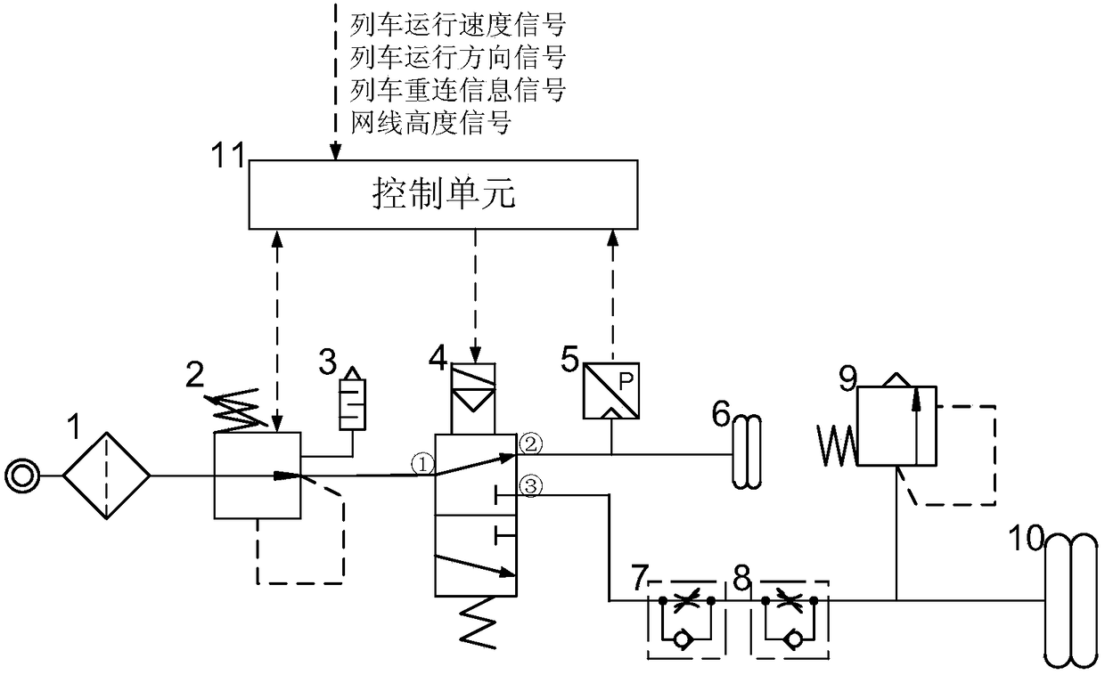
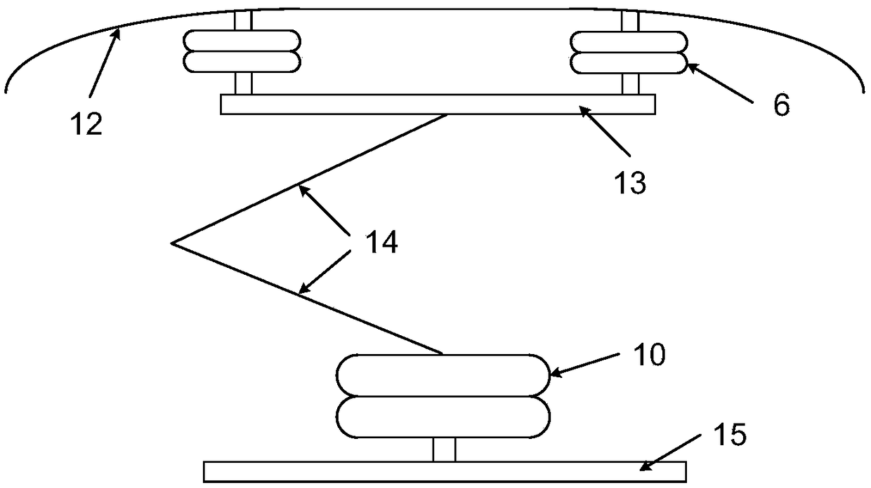
[0031] The pantograph control device uses the bow head airbag 6 and the pressure sensor 5 to detect the contact force between the pantograph and the catenary, and uses closed-loop control to adjust the pantograph-catenary contact force. The control device has the advantages of small adjustment error of the pantograph-catenary contact force and strong ability to suppress interference, thereby reducing energy consumption, prolonging the service life of the pantograph-catenary, improving the current receiving performance, and ensuring the safe and reliable operation of the train.

[0032] Such as figure 1 , figure 2 As shown, the pantograph control device includes an air filter 1, an electronically controlled pressure regulating valve 2, a muffler 3, a reversing solenoid valve 4, a bow throttle valve 7, a bow throttle valve 8, and a safety valve 9 . The bow airbag 10 also includes: a pressure sensor 5, a bow airbag 6 and a control unit 11;

[0033] The pantograph includes a ca...


PUM


Abstract

The invention discloses an air bag type pantograph closed-loop control device, comprising an air cleaner, an electrically controlled pressure regulating valve, a silencer, a reversing solenoid valve,a bow rising throttle valve, a falling bow throttle valve, a safety valve, a bow rising airbag, a pressure sensor, a bow head airbag and a control unit, wherein, the bow head airbag is connected between a carbon slide plate and a bow head bracket, the bow head airbag and the bow rising airbag are respectively connected with a reversing electromagnetic valve, and the pressure sensor is connected with an air path between the bow head airbag and the reversing electromagnetic valve. The pressure sensor, the electronically controlled pressure regulating valve and the reversing solenoid valve are respectively in signal connection with the control unit. The pressure data in the bow airbag installed between the carbon skate plate and the bow bracket is fed back to the control unit to realize the closed-loop control of pantograph-catenary contact force. The device can detect pantograph-catenary contact force in real time, and can adjust the pantograph-catenary dynamic contact force when pantograph is running at high speed according to the needs, so as to improve the quality of current collection and ensure the safe and reliable operation of the train.

Description

technical field [0001] The invention relates to a control technology for pantographs of electric locomotives and EMUs, in particular to an airbag type pantograph closed-loop control device. Background technique [0002] The pantograph is a high-voltage electrical device installed on an electric locomotive or EMU, and obtains electric energy to supply the vehicle through sliding friction with the contact wire. The pantograph completes the high-voltage current receiving through the contact between the carbon sliding plate of the bow head and the catenary. The reliable contact between the pantograph and the catenary is the basic condition to ensure good current receiving when the electric locomotive and EMU run at high speed. [0003] When the contact force between the pantograph and catenary is too small, the contact resistance is large, and the energy consumed is more, and the contact surface of the pantograph and catenary will generate more heat energy, which will easily cau...

Claims


Application Information

Patent Timeline
IPC IPC(8): B60L5/32
CPCB60L5/32
Inventor 马德彪高文斌吴荣平黄思俊郭玉瑾陈晓光
Owner BEIJING CED RAILWAY ELECTRIC TECH
Learn More