
An automobile rear longitudinal beam assembly and an automobile

A technology for rear longitudinal beams and automobiles, applied in the field of auto parts, can solve the problems of reducing the dimensional installation accuracy, increasing the welding process, unfavorable strength of the whole vehicle, etc., and achieving the effect of reducing the workload, eliminating the welding process, and having good safety performance.

Pending Publication Date: 2019-01-15
ZOTYE INT AUTOMOBILE TRADING CO LTD
View PDF0 Cites 3 Cited by
  • Summary
  • Abstract
  • Description
  • Claims
  • Application Information

AI Technical Summary

Problems solved by technology

[0003] 1. The rear longitudinal beam composed of multiple steel plate stamping parts needs to increase the welding process, which reduces the size and installation accuracy, increases the body gap, and brings resonance noise
[0004] 2. The rear longitudinal beam welded by multiple steel plate stamping parts must be matched with corresponding mounting plates, mounting supports and other parts in order to realize the connection with the chassis and body structures. Therefore, the number of parts increases and the process increases. At the same time Not conducive to vehicle weight reduction
[0005] 3. The segmented rear longitudinal beam requires an additional connection process between the front and rear sections of the rear longitudinal beam, which increases additional workload and is detrimental to the strength of the vehicle

Method used


Image

  • An automobile rear longitudinal beam assembly and an automobile
  • An automobile rear longitudinal beam assembly and an automobile
  • An automobile rear longitudinal beam assembly and an automobile

Examples


Embodiment Construction

[0026] In the present invention, it should be understood that the terms "length", "width", "upper", "lower", "front", "rear", "left", "right", "vertical", "horizontal" ", "Top", "Bottom", "Inner", "Outer", "Clockwise", "Counterclockwise", "Axial", "Plane Direction", "Circumferential" and other indications are based on The orientation or positional relationship shown in the drawings is only for the convenience of describing the present invention and simplifying the description, and does not indicate or imply that the referred device or element must have a specific orientation, be constructed and operated in a specific orientation, and therefore cannot be understood as Limitations on the Invention.

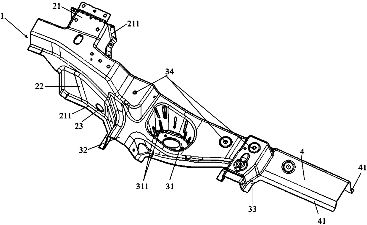
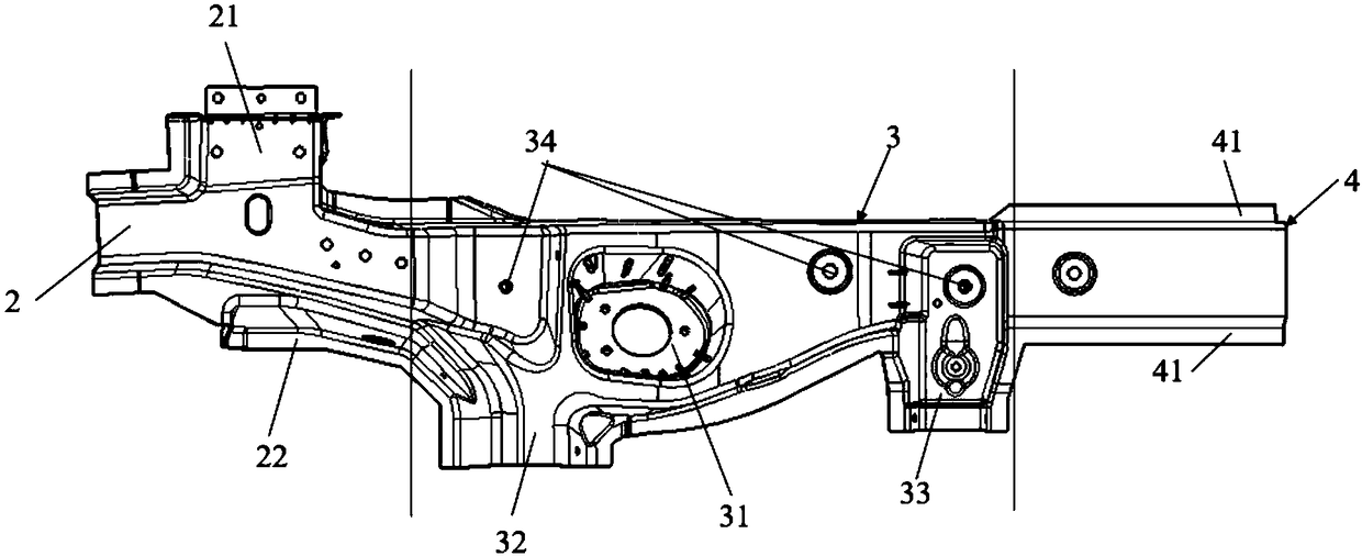
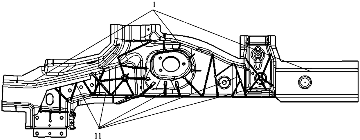
[0027] Such as figure 1 , figure 2 and image 3 As shown, a rear longitudinal beam assembly of an automobile comprises a rear longitudinal beam 1, the rear longitudinal beam 1 is integrally formed, and the rear longitudinal beam 1 includes a rear longitudinal beam front section ...


PUM


Abstract

A rear longitudinal beam assembly of an automobile comprises a rear longitudinal beam in an integrated molding structure, wherein the rear longitudinal beam comprises a front section of the rear longitudinal beam, a middle section of the rear longitudinal beam and a rear section of the rear longitudinal beam, the middle section of the rear longitudinal beam is arranged between the front section ofthe rear longitudinal beam and the rear section of the rear longitudinal beam, the end of the front section of the rear longitudinal beam is connected with a front longitudinal beam, and the end of the rear section of the rear longitudinal beam is connected with a rear retaining beam. The whole rear longitudinal beam is ladder-shaped, and the whole rear longitudinal beam is cast by aluminum alloy, and formed by high pressure casting process. A stiffener III is arranged inside the rear longitudinal beam, and the stiffener III is X-shaped or V-shaped. The stiffener III connects with each otherto form a reticulated structure, and the stiffener III improves the structural strength of the rear longitudinal beam. The rear longitudinal beam of the invention has the advantages of light weight, high integration, high installation precision, high strength, good safety performance and the like. The rear longitudinal beam is an integrated molding structure, which can reduce the quantity of partsand save the welding process between several parts, thus improving the machining accuracy and assembly accuracy of the parts.

Description

technical field [0001] The invention belongs to the technical field of auto parts, and relates to the lightweight technology of a vehicle body longitudinal beam, in particular to an automobile rear longitudinal beam assembly and an automobile. Background technique [0002] As one of the key parts of the car body, the rear longitudinal beam of the car body plays an important role in carrying the load and absorbing the impact of collisions in the car structure. Due to the long overall structure of the rear longitudinal beam, it is usually divided into two parts: the front section of the rear longitudinal beam and the rear section of the rear longitudinal beam. Since the rear longitudinal beam needs to be reasonably avoided and installed with other parts, the overall shape of the rear longitudinal beam is relatively complicated. Currently Common rear longitudinal beams are mostly welded by steel stamping parts, but this steel stamping structure has the following disadvantages: ...

Claims


Application Information

Patent Timeline
IPC IPC(8): B62D21/02B62D21/11B62D29/00
CPCB62D21/02B62D21/11B62D29/008
Inventor 张明珠牛丽媛李光玉程云张毅胡光山苏一畅熊建民朱小镇
Owner ZOTYE INT AUTOMOBILE TRADING CO LTD
Features
  • Generate Ideas
  • Intellectual Property
  • Life Sciences
  • Materials
  • Tech Scout
  • Unparalleled Data Quality
  • Higher Quality Content
  • 60% Fewer Hallucinations
Learn More