
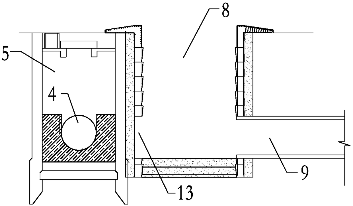
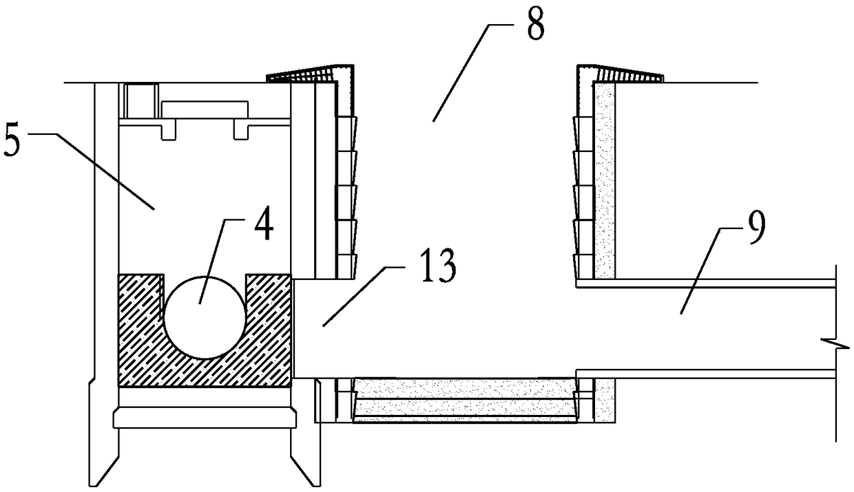
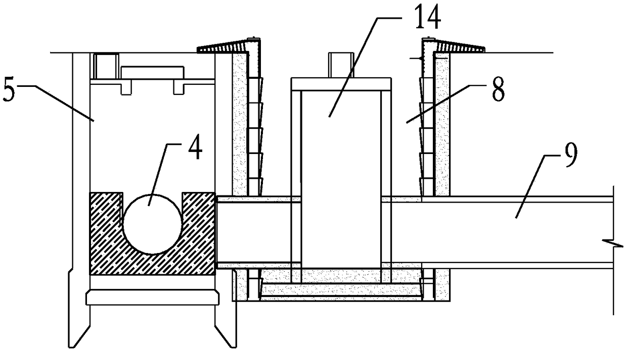
A construction method for new pipe connection and original pipe plugging in large-scale sewage pipeline relocation

A technology of sewage pipeline and construction method, which is applied in the field of submerged water, can solve the problems of water leakage, large impact force of water flow, and insufficient sealing of original pipeline, so as to reduce the impact force, reduce the impact force of water flow, and solve the problem of blockage puzzle effect

Pending Publication Date: 2019-01-15
URBAN MASS TRANSIT ENG CO LTD OF CHINA RAILWAY 11TH BUREAU GRP
View PDF0 Cites 14 Cited by
  • Summary
  • Abstract
  • Description
  • Claims
  • Application Information

AI Technical Summary

Problems solved by technology

[0002] With the rapid development of urban subways, during the subway construction process, there are often large sewage pipes across the station foundation pit. The most critical steps in the relocation process are the connection and sealing construction. Many projects have blocked the original pipes. If it is not in place, there will be a water leakage accident during the excavation of the foundation pit in the later stage
The plugging construction must be carried out by divers underwater. However, for large sewage pipelines, due to the strong impact force of the water flow, they do not have the conditions for diving operations at all. Therefore, how to ensure the sealing quality of the original pipeline after the large sewage pipeline is relocated becomes the primary solution. the puzzle

Method used


Image

  • A construction method for new pipe connection and original pipe plugging in large-scale sewage pipeline relocation
  • A construction method for new pipe connection and original pipe plugging in large-scale sewage pipeline relocation
  • A construction method for new pipe connection and original pipe plugging in large-scale sewage pipeline relocation

Examples


Embodiment Construction

[0032] The present invention will be further described below in conjunction with the accompanying drawings and embodiments. The specific structure of the temporary blocking flashboard in the embodiment of the present invention is as follows Figure 9 with Figure 10 As shown, it includes a grid steel frame 1 and a steel baffle 2. The steel baffle 2 is a thick steel plate with a thickness of 20 mm. The shape of the arc; the grid steel frame 1 is a shaped steel grid bracket that is welded by channel steel and has the same shape as the steel baffle plate 2, and a plurality of supports 3 are arranged on the rear side of the grid steel frame 1, The grid steel frame 1 adopts 40#a channel steel, and the support member 3 adopts H20 type steel. The distance between two adjacent horizontal and vertical channel steels in the grid steel frame 1 is 500mm. The shapes of the grid steel frame 1 and the upper part of the steel baffle plate 2 are matched with the inner cavity of the existing...


PUM

PropertyMeasurementUnit
Thicknessaaaaaaaaaa
Thicknessaaaaaaaaaa

Abstract

The invention provides a construction method for new pipe connection and original pipe plugging in large-scale sewage pipeline relocation. The construction method comprises the following steps: firstly, a new pipe receiving well is constructed beside an existing working well adjacent to the original sewage pipe, and the shaft wall of the existing working well is sawn, so that the new pipe receiving well is communicated with the existing working well; and then the original sewage pipe is temporarily plugged by adopting temporary plugging gate in the existing working well, wherein the temporaryplugging gate comprises a grille steel frame and a steel baffle. After the temporary plugging gate is installed, the diver goes down the shaft and plugs the original sewage pipe at the downstream partof the temporary plugging gate with brick masonry stone. After the plugging is completed, the underwater concrete is poured between the temporary gate valve and the plugs. The method adopts a temporary gate for temporary blocking, which can reduce the impact force of water flow on the diver and the blocking wall, reduce the operation risk, improve the blocking construction quality, and reduce theconstruction risk in the excavation process of the deep foundation pit of the metro.

Description

technical field [0001] The invention relates to the connection of old and new pipelines and the plugging construction of the original pipeline after the relocation of large-scale sewage pipelines. Specifically, it is a method of constructing a new pipe receiving well outside the existing sewage working well, and connecting the new pipe receiving well with the original pipeline. The pipe work well is connected, and then a temporary ram is set in the original pipe work well to create a safe environment for divers to work underwater, and then the sewage pipe is blocked. Background technique [0002] With the rapid development of urban subways, during the subway construction process, there are often large sewage pipes across the station foundation pit. The most critical steps in the relocation process are the connection and sealing construction. Many projects have blocked the original pipes. If it is not in place, water leakage accidents will occur during the excavation of the f...

Claims


Application Information

Patent Timeline
IPC IPC(8): E03F3/06E03F7/02
CPCE03F3/06E03F7/02
Inventor 曹祝华聂承庆徐伟张幸举李应姣王宏斌邱拥军
Owner URBAN MASS TRANSIT ENG CO LTD OF CHINA RAILWAY 11TH BUREAU GRP
Learn More