Method for manufacturing artificial borehole wall by saturated filling of bondable gravel around wellbore

A technology of cementing sand and gravel and artificial well wall, which is applied in wellbore/well components, chemical instruments and methods, earthwork drilling and production, etc., and can solve problems such as blockage and difficulty in extubation.

Active Publication Date: 2019-01-15
韩阳 +1
View PDF17 Cites 4 Cited by
  • Summary
  • Abstract
  • Description
  • Claims
  • Application Information

AI Technical Summary

Problems solved by technology

Although these patented technologies have their own advantages, they stil

Method used


Image

  • Method for manufacturing artificial borehole wall by saturated filling of bondable gravel around wellbore
  • Method for manufacturing artificial borehole wall by saturated filling of bondable gravel around wellbore
  • Method for manufacturing artificial borehole wall by saturated filling of bondable gravel around wellbore

Examples


Embodiment 1

[0095] Construction well example 1: Well BZ34-1-A18H (CNOOC Bozhong Oilfield - sandstone screen horizontal well)

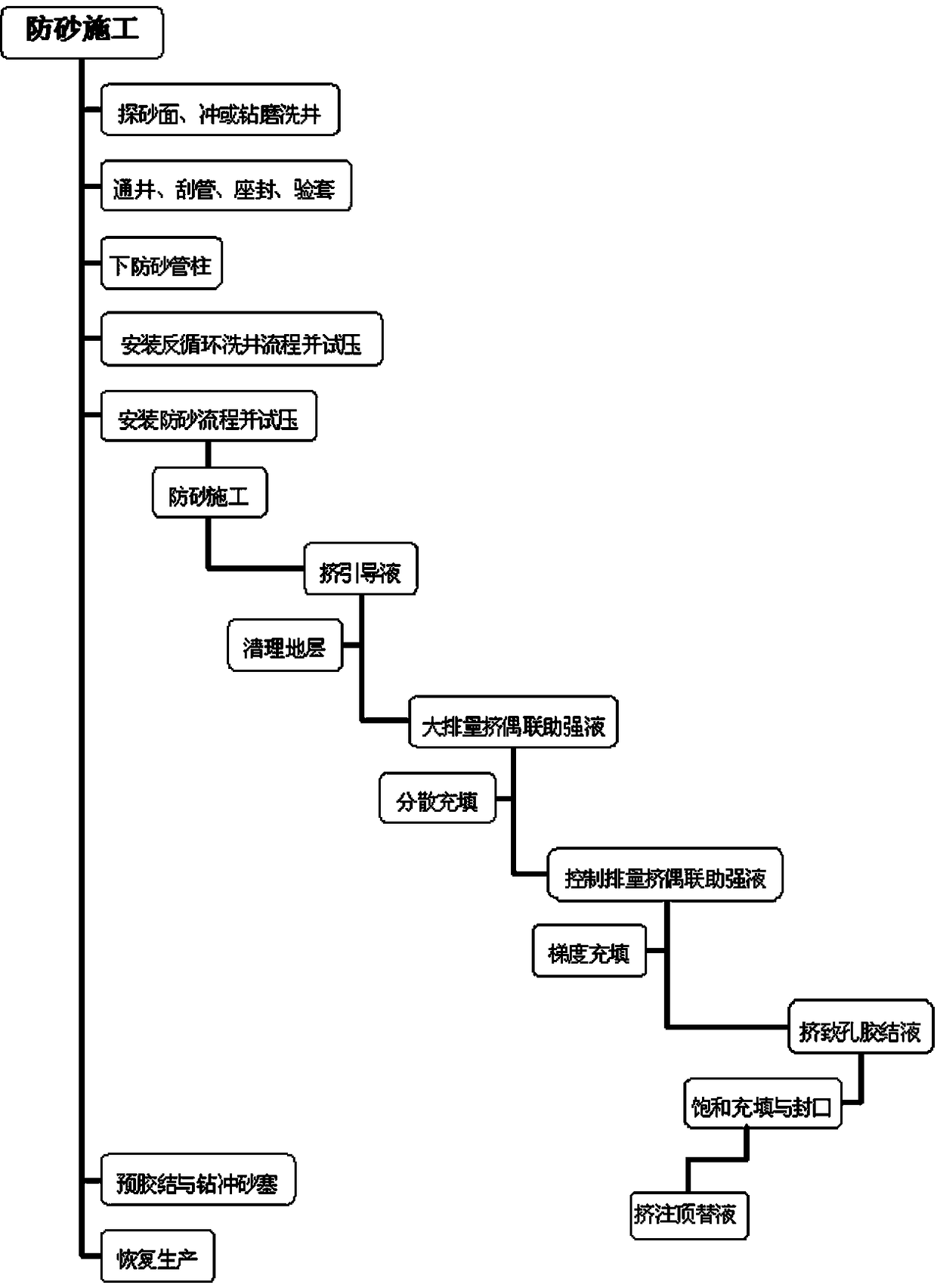
[0096] see Figure 4 , when the well started construction, the displacement was gradually increased to 2.6m 3 / min, the pump pressure rises to 13.3MPa, and the pollutants are cleaned with a large amount of cementable sand guide fluid, that is, the front fluid. The cementable sand guide fluid is composed of: chelating agent 2.0%, surfactant 3.0%, hydrochloric acid 5.0% , Anti-swelling agent 5.0%. Wherein the chelating agent is selected as ethylenediaminetetraacetic acid or diethylenetriaminepentamethylenephosphonic acid;

[0097] Surfactant includes: 1.5% alkyl polyoxyethylene ether with cloud point ≦30℃, 1.5% alkyl polyoxyethylene ether with cloud point ≥100℃; anti-swelling agent is NH4CL.

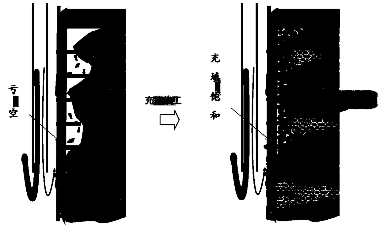
[0098] Then use the coupling strengthening fluid, that is, the sand-carrying fluid, to carry the cementable gravel into the void zone of the formation, and control the sand...

Embodiment 2

[0103] Construction well example 2: Well YM2-22 (PetroChina Tarim Yingmaili Oilfield - limestone open hole vertical well)

[0104] see Figure 5 , when the well started construction, the displacement was gradually increased to 2.7m 3 / min, the pump pressure is increased to 25MPa, and the pollutants are cleaned with a large displacement of the cementable sand guide fluid, that is, the front fluid, including 1.5% chelating agent, 3.0% surfactant, 7.0% hydrochloric acid, and 2.50% anti-swelling agent. Among them, the chelating agent is selected as ethylenediaminetetraacetic acid or diethylenetriaminepentamethylenephosphonic acid; the surfactant includes: 1.5% alkyl polyoxyethylene ether with a cloud point ≦30°C, and 1.5% with a cloud point ≥100°C The alkyl polyoxyethylene ether; the anti-swelling agent is NH4CL.

[0105] Then use the coupling strengthening fluid, that is, the sand-carrying fluid, to carry the cementable gravel into the void zone of the formation, and control th...


PUM

PropertyMeasurementUnit
Cloud pointaaaaaaaaaa

Abstract

The invention discloses a method for manufacturing an artificial borehole wall by saturated filling of bondable gravel around the wellbore, which is a new special sand control and collapse preventiontechnology for supporting the rock face and stabilizing the sand body through implementing saturated filling of the bondable gravel around the wellbore by adopting a high-flow-rate and high-pump-pressure end screening-out filling mode. The method comprises the steps of firstly effectively cleaning a flow guide channel by using a prepad fluid, relieving the resistance imposed on construction drainage by a micro-solid and high-density fluid, then conveying the bondable gravel to the end parts of deficit zone rocks by a low-flow-resistance carrier fluid, enabling the fluid to be drained on the rock surface to perform filter pressing on the bondable gravel so as to form an artificial sand belt, continuously filling until all deficits are filled, thus achieving saturated filling to form the artificial sand wall. The strength of the artificial sand wall is improved by thermal solidification so as to achieve a purpose of repairing and prolonging the service life of the production well.

Description

technical field [0001] The invention relates to a method for exploiting or injecting oil, gas, and water from wells in industries such as petroleum, natural gas, coal bed methane, geothermal water, and hot dry rock, and belongs to the technical field of preventing sand production and collapse of oil, water, and gas wells, especially The invention relates to a method for manufacturing an artificial well wall by saturating and filling cementable gravel around the wellbore. Background technique [0002] In the process of oil, natural gas, coal bed methane, geothermal water, hot dry rock and other industries extracting or injecting oil, gas, and water from the well, the edge of the well wall is washed by the fluid, causing the gravel to break away from the matrix and fall off the rock surface In severe cases, the rocks lose their support and cause block collapse, which is extremely harmful to oil, gas, and water wells. If gravel or falling blocks are used to bury oil, gas, and ...

Claims


Application Information

Patent Timeline
IPC IPC(8): E21B43/02C09K8/575
CPCC09K8/5755E21B43/02
Inventor 韩阳杨小平
Owner 韩阳
Why Eureka
Try Eureka