
High back pressure steam turbine unit

A steam wheel, high back pressure technology, applied in mechanical equipment, engine components, machines/engines, etc., can solve problems such as the inability to adjust the size of the nozzle outlet according to the needs, the impossibility to adjust the impulsive force of the moving blades, and the heat dissipation of hot steam. The effect of reducing heat dissipation, improving practicality, and improving conversion efficiency

Active Publication Date: 2019-01-15
府谷科创源能源科技股份有限公司
View PDF11 Cites 4 Cited by
  • Summary
  • Abstract
  • Description
  • Claims
  • Application Information

AI Technical Summary

Problems solved by technology

[0003] During the use of the existing back-pressure steam turbine unit, when the hot steam is passed into the steam inlet pipe, due to the low temperature near the steam inlet pipe, it is easy to cause the heat loss of the hot steam. The existing impulsive mechanism generally uses steam Expansion occurs in the nozzle, the pressure decreases, the speed increases, and the heat energy is converted into kinetic energy. When the high-speed airflow passes through the moving blade, due to the change of the airflow direction, an impulsive force is generated on the moving blade, which pushes the impeller to rotate and do work, and the southeast of the steam It becomes the mechanical energy of the shaft rotation, but the nozzle of the existing high back pressure steam turbine unit cannot adjust the outlet size of the nozzle according to the demand, so that the impulsive force of the air flow on the moving blade cannot be adjusted. Therefore, we propose a high back pressure steam turbine

Method used


Image

  • High back pressure steam turbine unit
  • High back pressure steam turbine unit
  • High back pressure steam turbine unit

Examples


Embodiment

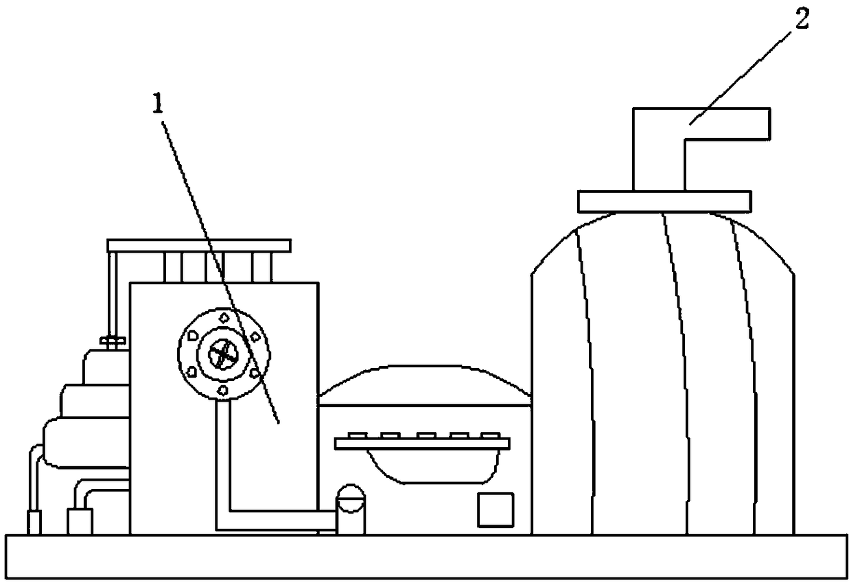
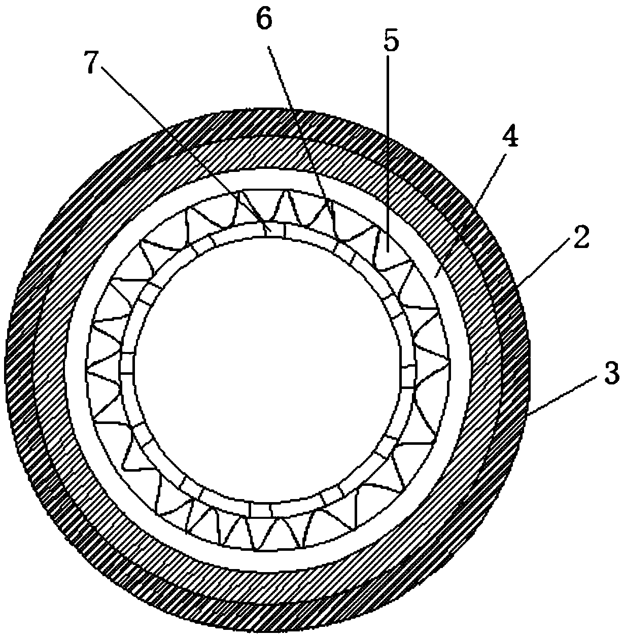
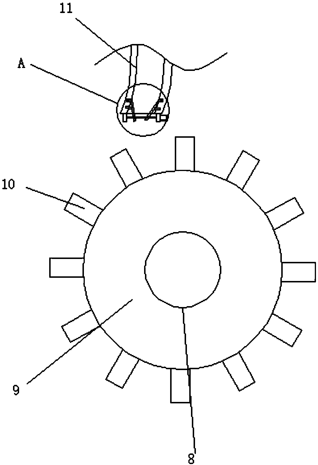
[0029] Embodiment: When adjusting the ejection aperture of the nozzle 11, by starting the driving motor 14, the driving motor 14 drives the transmission shaft 15 to rotate, and the transmission shaft 15 drives the adjustment plates 19 to approach or move away from each other through screw transmission, and the adjustment plates 19 are in the During the moving process, the connecting plate 18 and the guide rod 21 are used for guiding. At the same time, the sealing gasket provided improves the sealing performance between the adjusting plate 19 and the inner wall of the nozzle 11, and the airflow ejected from the nozzle 11 blows the moving blade 10. , the impeller 9 is rotated, and at the same time, the heating wire 6 is started, and the heat generated by the heating wire 6 enters the inside of the steam inlet pipe 2 from the exhaust port 7, and the steam inlet pipe 2 is preheated and kept warm. The sleeve 3 can reduce the heat dissipation of the steam inlet pipe 2. The design is ...


PUM


Abstract

The invention discloses a high back pressure steam turbine unit, comprising a unit body. The unit body comprises an inlet duct and an impulse mechanism. The outside of the inlet duct is provided witha heat preservation mechanism, and the heat preservation mechanism comprises a joint mounted on the outer side wall of the inlet duct. The inner sleeve of the inlet pipe is fixed with an annular plate, the inner part of the annular plate is provided with a cavity, and the inner side of the cavity is connected with a heating wire, and the inner side wall of the annular plate is provided with an exhaust port along the axial array direction thereof. The exhaust port communicates with the interior of the cavity. The impulse mechanism includes a rotating shaft, an impeller, a moving blade and a nozzle. The outer side wall of the rotating shaft is fixed with an impeller. The outer sidewall of the impeller is fixed with a plurality of symmetrically disposed moving blades along the axial array direction. The steam turbine unit can adjust the spray outlet diameter of the nozzle, thereby adjusting the speed at which the steam flow is ejected from the nozzle to adjust the rotation speed of the impeller, and improving the conversion efficiency. Moreover, the steam turbine unit can achieve the heat preservation heating of the inlet duct to reduce the heat dissipation of steam.

Description

technical field [0001] The invention relates to the technical field of back pressure units, in particular to a high back pressure steam turbine unit. Background technique [0002] The back pressure unit is a generator unit that adjusts the power generation load by the thermal load, that is to say, the power generation varies with the amount of steam supplied from the outside, and how much steam the steam turbine enters and how much steam is exhausted by the unit. Therefore, the economy of the back-pressure steam turbine is better, and the extraction steam turbine can generate electricity purely or supply heat to the outside through air extraction. Changes in load are adjusted accordingly to ensure the economical operation of the unit. [0003] During the use of the existing back-pressure steam turbine unit, when the hot steam is passed into the steam inlet pipe, due to the low temperature near the steam inlet pipe, it is easy to cause the heat loss of the hot steam. The exi...

Claims


Application Information

Patent Timeline
IPC IPC(8): F01D17/14F01D25/10
CPCF01D17/14F01D25/10
Inventor 陈济颖牛峥
Owner 府谷科创源能源科技股份有限公司
Learn More