
Silencer for air conditioning and air conditioner

A technology for mufflers and air conditioners, applied in the field of air conditioners, can solve the problems of complex structure, narrow sound-absorbing frequency band, poor sound-absorbing effect, etc., and achieve the effect of improving user experience, increasing sound-absorbing frequency bands, and reducing high-frequency noise.

Pending Publication Date: 2019-01-15
GD MIDEA AIR-CONDITIONING EQUIP CO LTD
View PDF9 Cites 0 Cited by
  • Summary
  • Abstract
  • Description
  • Claims
  • Application Information

AI Technical Summary

Problems solved by technology

[0002] The commonly used mufflers for air conditioners are mostly of a single expansion chamber structure, which has a poor noise reduction effect and a narrow frequency band, which cannot achieve good noise reduction and noise reduction effects, and affects user experience.
[0003] In the related art, some composite mufflers have been proposed, such as connecting two independent mufflers in series to achieve the purpose of widening the muffler range, but the structure is complex, the manufacturing cost is high, and the length of the muffler is long, so it cannot comprehensively muffle the sound. Effects and Piping Spatial Layout

Method used


Image

  • Silencer for air conditioning and air conditioner
  • Silencer for air conditioning and air conditioner
  • Silencer for air conditioning and air conditioner

Examples


Embodiment 1

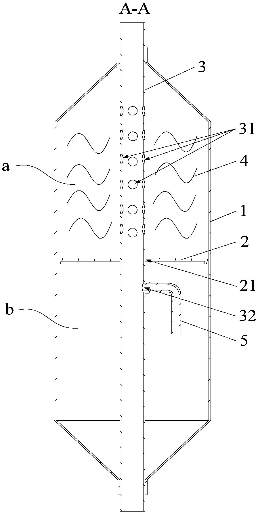
[0054] One end of the inner pipe 3 is an air inlet end, and the other end is an air outlet end, the air inlet end is located in the first pipe section, and the air outlet end is located in the second pipe section.

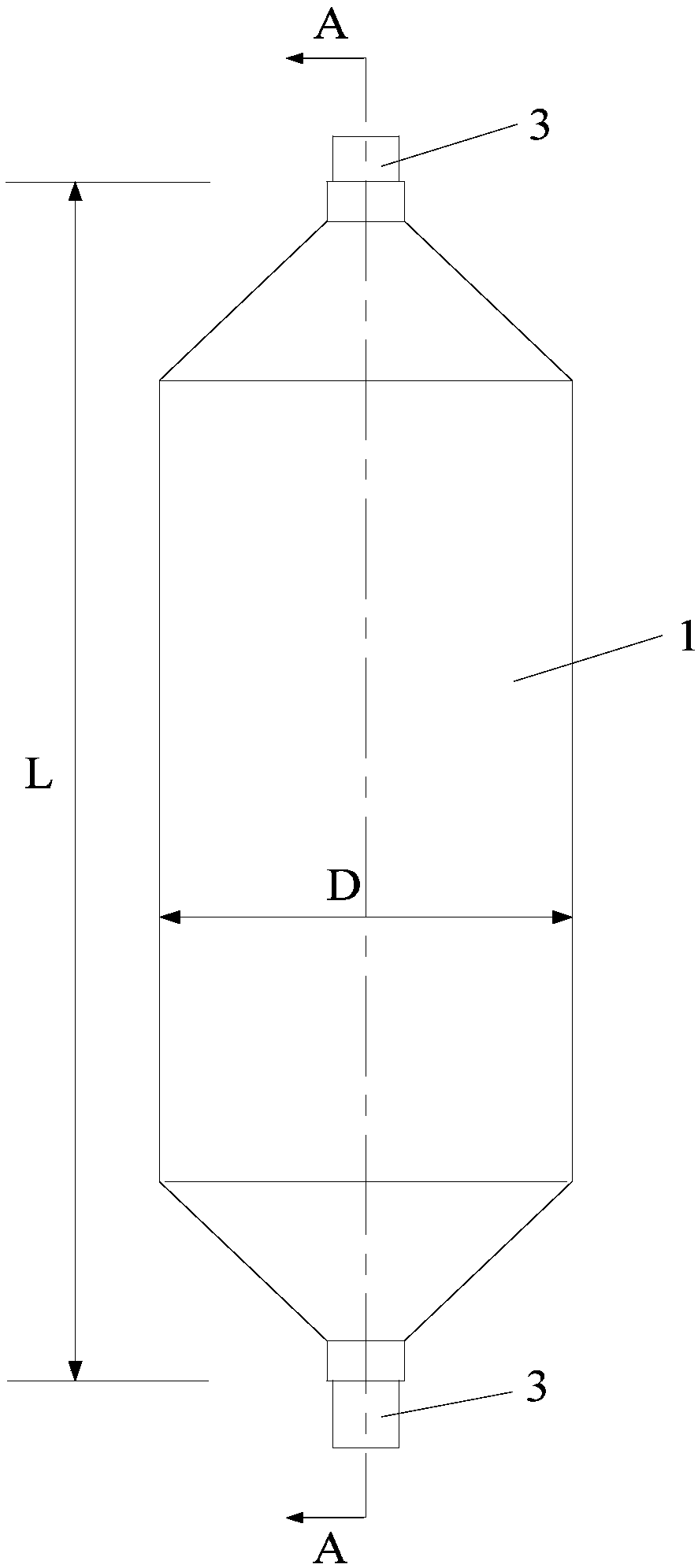
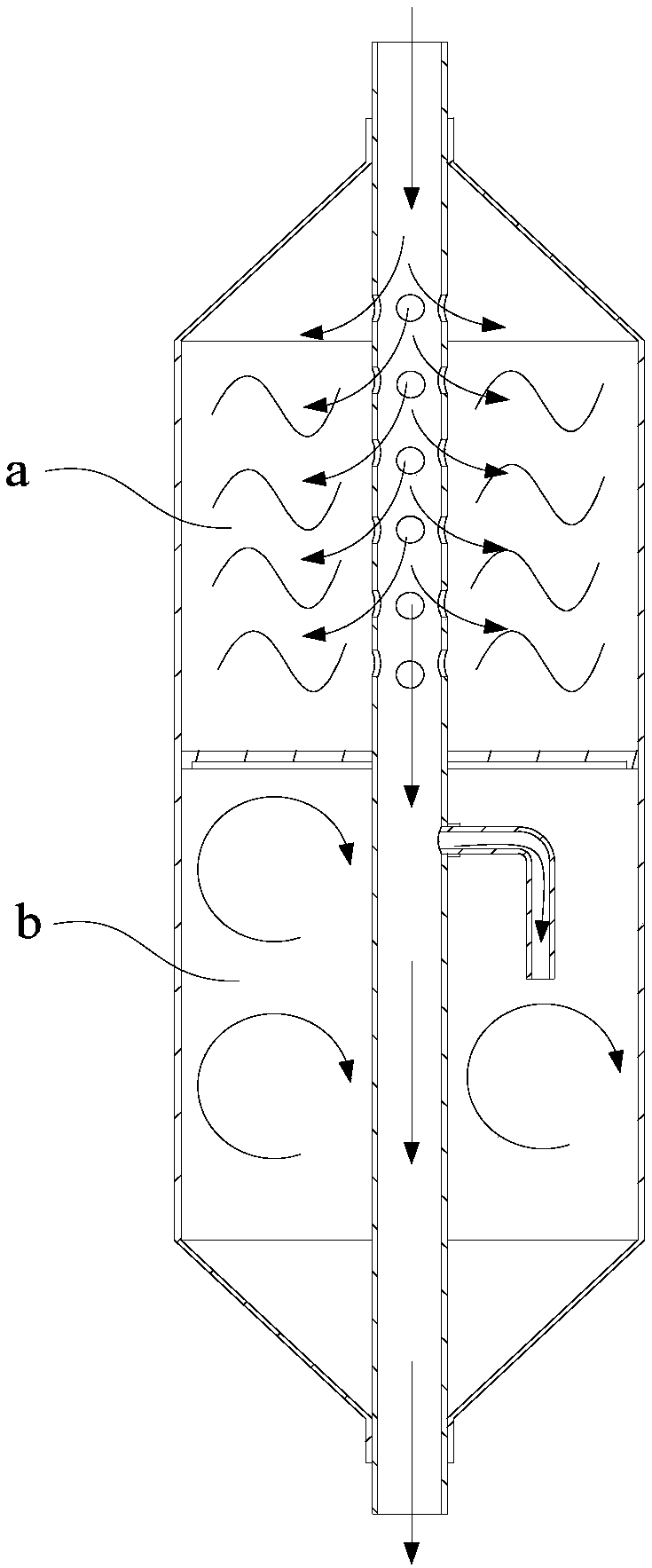
[0055] Specifically, the muffler for an air conditioner includes an outer cylinder 1, an inner pipe 3, an inner partition 2, and sound-absorbing materials. In 1 / 2 room, an array of small holes (namely the first through hole 31) is opened on the tube, and the end of the array of small holes is opened. The inner partition 2 and the outer cylinder 1 form a sound-absorbing cavity a, and the sound-absorbing cavity a is filled with sound-absorbing materials; the inner tube 3 At the air outlet end, one or two small holes (that is, the second through hole 32) are opened on the pipe, and at the end of the small hole, the inner partition 2 and the outer cylinder 1 form the Helmholtz resonance chamber b; the air flow enters through the inner pipe 3 The air end enters the muff...

Embodiment 2

[0057] Such as Figure 1 to Figure 3 As shown, the difference between the second embodiment and the first embodiment is that the resonance tube 5 is connected to the second through hole 32, and the resonance tube 5 is entirely located in the Helmholtz resonance cavity b.

[0058] By connecting the resonance pipe 5 at the second through hole 32 of the second pipe section of the inner pipe 3, a specific frequency can be designed by adjusting the length of the resonance pipe 5, thereby combining the sound absorption and noise reduction of the sound absorption chamber a to eliminate the noise of a wider frequency band , so as to achieve the purpose of reducing or eliminating noise; preferably, the resonance tube 5 is inserted into the second through hole 32 and welded to the second section of the inner tube 3 .

[0059] Specifically, the air conditioner muffler includes an outer cylinder 1, an inner pipe 3, an inner partition 2, a sound-absorbing material 4, and a resonance pipe 5...

Embodiment 3

[0061] One end of the inner pipe 3 is an air inlet end, and the other end is an air outlet end, the air inlet end is located in the second pipe section, and the air outlet end is located in the first pipe section.

[0062] Specifically, the muffler for an air conditioner includes an outer cylinder 1, an inner pipe 3, an inner partition 2, and sound-absorbing materials. The second through hole 32), the small hole end is opened, the inner partition 2 and the outer cylinder 1 form the Helmholtz resonance chamber b; the inner tube 3 is the gas outlet end, and an array of small holes (i.e. the first through hole 31) is opened on the tube, At the end of an array of small holes, the inner partition 2 and the outer cylinder 1 form a sound-absorbing chamber a, and the sound-absorbing chamber a is filled with sound-absorbing materials; the airflow enters the muffler through the air inlet of the inner pipe 3, and part of the airflow enters through the small holes on the inner pipe 3 Helm...


PUM

PropertyMeasurementUnit
Middle diameteraaaaaaaaaa
Lengthaaaaaaaaaa
Lengthaaaaaaaaaa

Abstract

The invention provides a silencer for air conditioning and an air conditioner. The silencer for air conditioning comprises an outer cylinder, an inner separation plate and an inner tube, wherein the outer cylinder is provided with two oppositely arranged ports; the inner separation plate is arranged in the outer cylinder and divides the outer cylinder into a sound absorbing chamber and a Helmholtzresonance chamber, and the inner separation plate is provided with an insertion hole; the inner tube is inserted into the outer cylinder, passes through the insertion hole and is fixed with two endsof the outer cylinder, the inner tube includes a first tube section and a second tube section which take the inner separation plate as a boundary, at least part of the tube body of the first tube section is located in the sound absorbing chamber and is provided with first through holes, the sound absorbing chamber is internally filled with a sound absorbing material, at least part of the tube bodyof the second tube section is located in the Helmholtz resonance chamber and is provided with a second through hole. The silencer provided by the invention for air conditioning designs a two-stage silencer through arranging the inner separation plate in the outer cylinder and inserting the inner tube, thereby increasing the silencing frequency band, and improving the silencing performance. In addition, the silencer for air conditioning is simplified in structure, low in manufacturing cost and further conducive to synthesizing the silencing effect and the spatial layout of tubing.

Description

technical field [0001] The present invention relates to the technical field of air conditioners, more specifically, to an air conditioner muffler and an air conditioner including the air conditioner muffler. Background technique [0002] The commonly used mufflers for air conditioners are mostly of a single expansion chamber structure, which has a poor noise reduction effect and a narrow frequency range, which cannot achieve a good noise reduction effect and affects the user experience. [0003] Some composite mufflers have been proposed in the related art, for example, by connecting two independent mufflers in series to achieve the purpose of widening the muffler range. Effects and piping space layout. Contents of the invention [0004] The present invention aims to solve at least one of the technical problems existing in the prior art. [0005] Therefore, an object of one aspect of the present invention is to provide a muffler for an air conditioner. [0006] Another ...

Claims


Application Information

Patent Timeline
IPC IPC(8): F24F13/24
CPCF24F13/24F24F2013/242F24F2013/247
Inventor 路志明
Owner GD MIDEA AIR-CONDITIONING EQUIP CO LTD
Learn More