Synchronous calibration device and method for strain and temperature of distributed sensor fiber (cable)

A technology of sensing optical fiber and calibration method, applied in measurement devices, instruments, etc., can solve the problems of difficulty in distinguishing strain and temperature cross effects, large calibration result errors, inconsistent displacement of optical fiber cores, etc., and achieves a simple and easy test process. It is easy to operate, reduce the difficulty of calibration, and has a good performance-price ratio.

Active Publication Date: 2019-01-15
NANJING UNIV
View PDF8 Cites 4 Cited by
  • Summary
  • Abstract
  • Description
  • Claims
  • Application Information

AI Technical Summary

Problems solved by technology

The equal-intensity beam method is to paste the optical fiber on the equal-intensity beam, and use the deformation of the equal-intensity beam to generate strain on the optical fiber. This method requires manual operation, the accuracy is very poor, and the calibration results have large errors, making it difficult to meet the requirements. Moreover, the length of equal-strength beams is generally less than 2 meters, and the spatial resolution of commonly used demodulators is generally greater than 1 meter. The data points obtained are too few and often not representative
In addition, the strain gauge or dial gauge is used to measure and calculate the strain of the equal-intensity beam, but there is glue between the equal-intensity beam and the optical fiber, which is not completely coupled, resulting in the strain of the equal-intensity beam being equal to that of the optical fiber. Strain cannot be transmitted directly, and corresponding errors will also occur
[0004] The fixed-point stretching method is to fix the optical fiber with a clamp on the displacement platform, accurately measure the distance between the two clamps, and use an electric or hydraulic displacement device to apply tension to the optical fiber. The displacement of the displacement platform is used as the deformation of the optical fiber in the stretched section. The functional relationship between the strain parameter and the act...

Method used


Image

  • Synchronous calibration device and method for strain and temperature of distributed sensor fiber (cable)
  • Synchronous calibration device and method for strain and temperature of distributed sensor fiber (cable)
  • Synchronous calibration device and method for strain and temperature of distributed sensor fiber (cable)

Examples


Embodiment

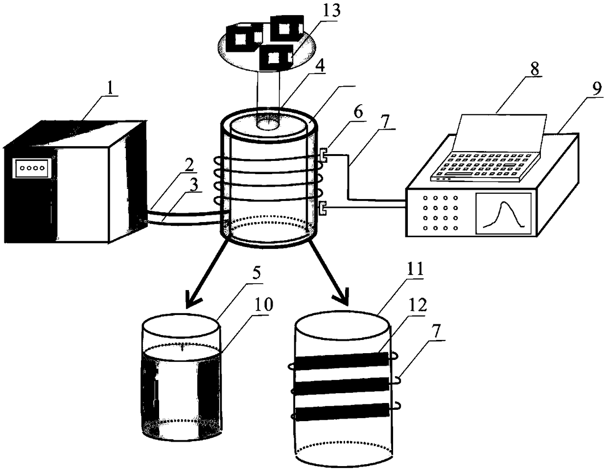
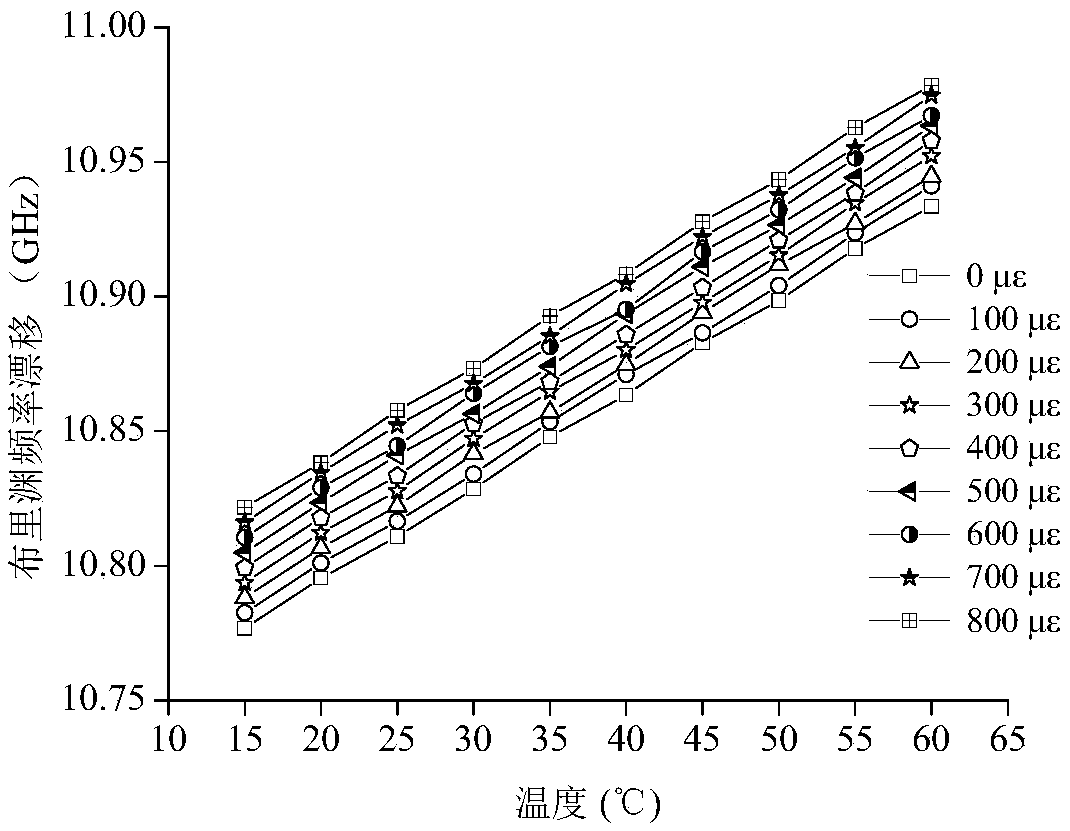
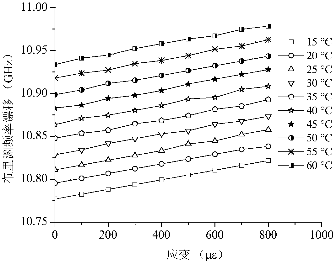
[0046] Such as figure 1 As shown, a distributed sensing optical fiber (cable) gauge coefficient and temperature coefficient calibration device includes: 1. Temperature control box, 2. Insulated liquid inlet pipe, 3. Temperature control device, 4. Weight connecting rod, 5. Inside of the calibration barrel, 6. Optical fiber fixture, 7. Calibration optical fiber, 8. Data processor, 9. Distributed optical fiber demodulator, 10. Liquid level, 11. Outer wall of the calibration barrel, 12. Outer wall groove, 13. Weight . The distributed optical fiber interrogator is a Brillouin Optical Time Domain Reflectometry Optical Fiber Strain / Temperature Measuring Instrument (BOTDR), the model of which is AV6419. The height of the calibration barrel is 20cm, the radius of the bottom surface is 6cm, and the barrel volume is small, which is easy to carry and test; the calibration column is hollow, and the preferred groove depth of the thread on its side surface is 2mm, and the interval is 5mm; t...


PUM

PropertyMeasurementUnit
Diameteraaaaaaaaaa

Abstract

The invention discloses a synchronous calibration device and method for strain and a temperature of a distributed sensor fiber (cable). The synchronous calibration method comprises the following stepsof uniformly winding fibers (cables) to be calibrated around an outer wall of a calibration barrel during calibrating a strain coefficient, gradually adding weights, calculating hoop strain of the calibration barrel under different loads according to elastic modulus of the calibration barrel and poisson ratio, reading spectrum information under each level of load by a fiber data demodulator, building a relation between the hoop strain and the spectrum information, and calibrating the strain coefficient; achieving control on a temperature of the calibration barrel by a temperature control boxduring calibrating a temperature coefficient, acquiring the spectrum information under different temperatures by the demodulator, and calibrating the temperature coefficient. By the synchronous calibration method, the strain coefficient and the temperature coefficient can be independently or synchronous calibrated, the strain generated by an external force effect and the influence of environmentaltemperature change on the spectrum information can be simultaneously determined, the cross effect between the strain and the influence is analyzed, and a calibration effect has high accuracy and is more confirm to an actual application condition.

Description

technical field [0001] The invention relates to the technical field of distributed sensing optical fiber (cable) sensor calibration, in particular to a strain and temperature synchronous calibration device and method for distributed sensing optical fiber (cable). Background technique [0002] In distributed fiber optic sensing systems, using optical fibers as sensors, changes in strain or temperature can be monitored in real time. When the external temperature or strain changes, the optical fiber wavelength, frequency and other spectral information changes are analyzed by the demodulator, and then the temperature or strain is obtained through theoretical calculation. Before using this method, you must first determine the gauge coefficient and temperature coefficient of the optical fiber under test in the theoretical formula. The two coefficients are related to the material of the optical fiber and are physical parameters of the optical fiber itself. They cannot be tested dir...

Claims


Application Information

Patent Timeline
IPC IPC(8): G01D21/02G01D18/00
CPCG01D18/00G01D21/02
Inventor 朱鸿鹄吴海颖曹鼎峰张巍施斌
Owner NANJING UNIV
Why Eureka
Try Eureka