
Oxygen removal device for corrosion test solution and operation method thereof

A corrosion test and solution technology, applied in measuring devices, weather resistance/light resistance/corrosion resistance, instruments, etc., can solve problems such as invalid results and large deviations in corrosion test results, achieve convenient operation, avoid oxygen corrosion problems, low cost effect

Pending Publication Date: 2019-01-15
BC P INC CHINA NAT PETROLEUM CORP +1
View PDF0 Cites 2 Cited by
  • Summary
  • Abstract
  • Description
  • Claims
  • Application Information

AI Technical Summary

Problems solved by technology

However, the closed environment of oil and gas production is an oxygen-free environment. When the laboratory uses the corrosion test method to evaluate the corrosion resistance of metal materials, if the dissolved oxygen in the corrosion test solution is not effectively removed, the contribution of dissolved oxygen to metal corrosion is much greater than that of other methods. Corrosion factors (such as CO 2 and H 2 S), resulting in a large deviation in the corrosion test results
[0004] At present, most laboratories pass inert gas (such as nitrogen) into the corrosion test solution to drive away the dissolved oxygen in the solution, but there are still two problems: (1) Deoxygenation is usually done between the corrosion test solution and the metal test solution. Oxygen corrosion in the early stage of the test is inevitable; (2) If there are easily oxidized cations in the corrosive environment of the oil and gas field, the corrosion test will cause invalid results due to the oxidation of cations by dissolved oxygen

Method used


Image

  • Oxygen removal device for corrosion test solution and operation method thereof

Examples


Embodiment Construction

[0034]In the description of the present invention, it should be understood that the orientation or positional relationship indicated by the terms "bottom", "inner", "outer", etc. is based on the orientation or positional relationship shown in the drawings, and is only for the convenience of describing the present invention and simplified descriptions, rather than indicating or implying that the device or element referred to must have a specific orientation, be constructed and operate in a specific orientation, and thus should not be construed as limiting the invention. In addition, the terms "first" and "second" are used for descriptive purposes only, and cannot be interpreted as indicating or implying relative importance or implicitly specifying the quantity of indicated technical features. Thus, a feature defined as "first" and "second" may explicitly or implicitly include one or more of these features. In the description of the present invention, unless otherwise specified,...


PUM


Abstract

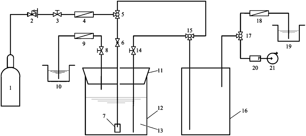
The invention discloses an oxygen removal device for a corrosion test solution and an operating method thereof. The oxygen removal device for a corrosion test solution comprises a high-purity nitrogenbottle, a glass bottle and a sealed container for a corrosion test. The high-purity nitrogen bottle is divided into two paths through a first three-way valve, one path is connected with the glass bottle filled with the corrosion test solution, and the other path is connected with a second three-way valve. The second three-way valve is divided into two paths connected with the glass bottle and thesealed container for the corrosion test respectively. The sealed container for the corrosion test is connected with a vacuum pump and a tail gas treatment container separately through a third three-way valve. According to the oxygen removal device for a corrosion test solution, the structure is simple, the assembly is easy, the operation is convenient, the cost is low; the oxygen removal device for a corrosion test solution can effectively remove the dissolved oxygen content in the corrosion test solution, can effectively avoid the oxygen corrosion problem existing in the current metal corrosion test process, and improve the accuracy and the effectiveness of metal corrosion test evaluation.

Description

technical field [0001] The invention belongs to the technical field of metal corrosion experiments, and in particular relates to an oxygen removal device for a corrosion test solution and an operation method thereof. Background technique [0002] In oil and gas field production, oil casing and pipelines are often due to CO 2 、H 2 The corrosion of S, elemental sulfur, and formation water causes oil and gas leakage accidents, resulting in environmental pollution, personal injury and economic losses, and seriously threatens the production and operation of oil and gas fields. [0003] In order to ensure the safe production of oil and gas fields, the laboratory corrosion test method is usually used to evaluate the adaptability of oil casing and delivery pipes in the production conditions of oil and gas fields. However, the dissolved oxygen in the corrosion test solution often leads to the inaccuracy of the corrosion test results. Oxygen is a part of the air and is the main fac...

Claims


Application Information

Patent Timeline
IPC IPC(8): G01N17/00
CPCG01N17/006
Inventor 袁军涛张慧慧付安庆李发根吕乃欣李磊
Owner BC P INC CHINA NAT PETROLEUM CORP
Learn More