Socket connectors, plug connectors and connector assemblies

A socket connector and base technology, which is applied to the parts, connections, fixed/insulated contact members of the connection device, etc., can solve the problems of inability to realize vacuum and vacuum electronic products, and achieve low cost and high voltage insulation. Performance, compact structure

Pending Publication Date: 2019-01-15
NUCTECH CO LTD +1
View PDF0 Cites 0 Cited by
  • Summary
  • Abstract
  • Description
  • Claims
  • Application Information

AI Technical Summary

Problems solved by technology

However, the existing aviation sockets usually use organic materials such as rubber as insulators. On ordinary electrical equipment, only insulation or further isolation of water, oil and other substances is required, and vacuum cannot be achieved, especially for high-vacuum isolation and sealing. Vacuum electronic products with high vacuum isolation requirements inside and outside the socket

Method used


Image

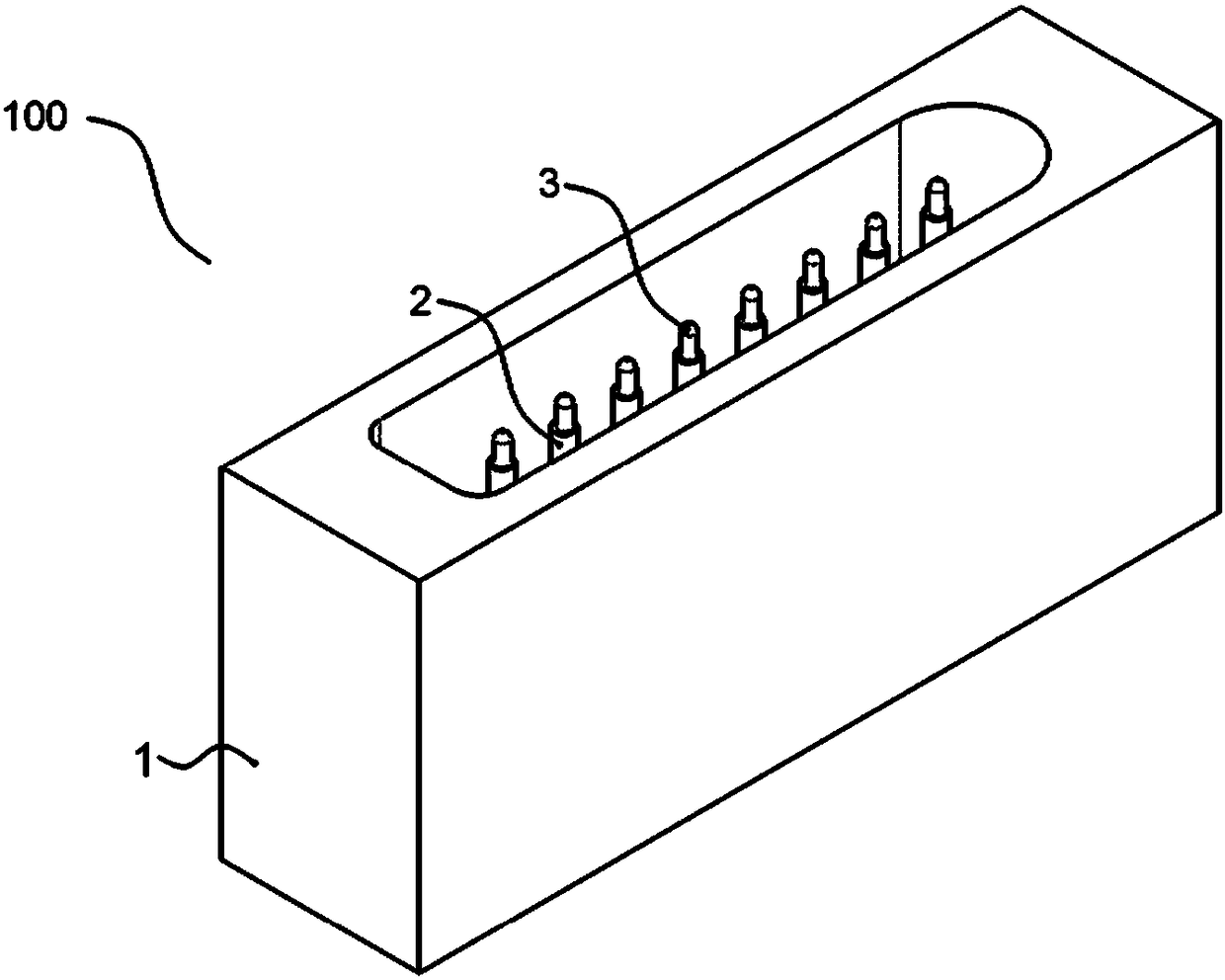
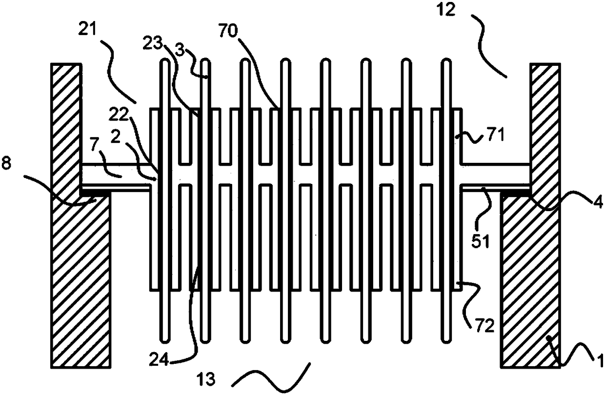
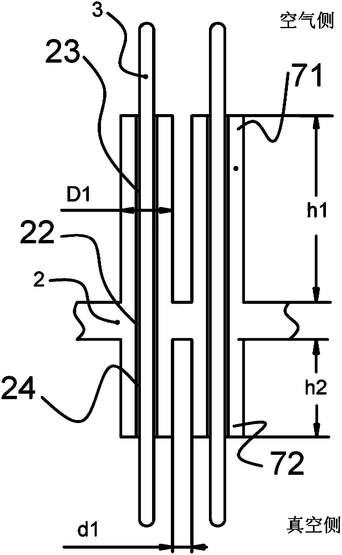
  • Socket connectors, plug connectors and connector assemblies
  • Socket connectors, plug connectors and connector assemblies
  • Socket connectors, plug connectors and connector assemblies

Examples


Embodiment Construction

[0080] The technical solutions of the present invention will be further specifically described below through embodiments and in conjunction with the accompanying drawings. In the specification, the same or similar reference numerals designate the same or similar components. The following description of the embodiments of the present invention with reference to the accompanying drawings is intended to explain the general inventive concept of the present invention, but should not be construed as a limitation of the present invention.

[0081] In addition, in the following detailed description, for purposes of explanation, numerous specific details are set forth in order to provide a comprehensive understanding of the embodiments of the present disclosure. It may be evident, however, that one or more embodiments may be practiced without these specific details. In other instances, well-known structures and devices are shown in diagrammatic form to simplify the drawings.

[0082]...


PUM

PropertyMeasurementUnit
Heightaaaaaaaaaa
Diameteraaaaaaaaaa
Depthaaaaaaaaaa

Abstract

The invention discloses a socket connector, a plug connector and a connector assembly. The socket connector comprises a housing made of a metal material, and a first through hole is formed in the housing; A ceramic insulator comprising a base fixed in a first through hole and sealingly connected to a housing, and one or more bosses provided with a plurality of second through holes in the base, thebosses extending in an axial direction from at least one side of both sides of the base, each boss provided with an auxiliary through hole communicating with the second through hole; And a pluralityof conductive terminals respectively passing through the second through-hole and the auxiliary through-hole and sealingly mounted to the ceramic insulator.

Description

technical field [0001] Embodiments of the present invention relate to an electrical connector, and in particular, to a socket connector, a plug connector and a connector assembly. Background technique [0002] Ceramic lead terminals (also ceramic electrodes or ceramic insulators) mainly include conductive terminals and ceramic insulators for supporting conductive terminals, which utilize the high insulation performance and mechanical strength of ceramics, and have a very wide range of electrical connections, especially high-voltage electrical connections. application. Due to the metallization of the ceramic surface, the ceramic is welded to the metal after metallization, and the surface has certain mechanical properties and temperature characteristics to achieve vacuum sealing, so the application of ceramic lead terminals in electronic vacuum devices is very common. In particular, when used as an electrical connection device for electronic vacuum devices, ceramic lead termi...

Claims


Application Information

Patent Timeline
IPC IPC(8): H01R13/40H01R13/405H01R13/52
CPCH01R13/40H01R13/405H01R13/5202H01R13/521
Inventor 陈志强唐华平李元景赵自然刘耀红秦占峰王永刚
Owner NUCTECH CO LTD
Why Eureka
Try Eureka