
Vacuum air inlet system and air inlet control method thereof

An air intake system and vacuum technology, used in pump control, liquid variable capacity machinery, variable capacity pump components, etc. The experimental site is not allowed to enter, etc., to achieve the effect of safe, stable and reliable work, convenient installation and disassembly, and convenient and simple operation.

Pending Publication Date: 2020-05-05
HEFEI INSTITUTES OF PHYSICAL SCIENCE - CHINESE ACAD OF SCI
View PDF7 Cites 0 Cited by
  • Summary
  • Abstract
  • Description
  • Claims
  • Application Information

AI Technical Summary

Problems solved by technology

Otherwise, when the internal pressure of the vacuum chamber is greater than the external atmospheric pressure, on the one hand, it is easy to cause damage to the internal devices, and on the other hand, the safety valve on the vacuum chamber will be activated to release excess gas, which will cause problems in the vacuum seal.
In addition, the existing method of monitoring the internal pressure of the vacuum chamber is to observe through the gauge and vacuum gauge connected to the vacuum chamber, but the difference in gas composition will cause great differences in vacuum measurement, and it is impossible to accurately feedback the internal pressure of the vacuum chamber
This makes it impossible for us to accurately judge whether to close the intake stop valve
Because this air intake mode requires on-site operation, and during the experiment, the experimental site is not allowed to enter, which will greatly affect the progress of the experiment
Moreover, the air intake process takes a long time, requires the staff to pay attention all the time, and is relatively tiring.

Method used


Image

  • Vacuum air inlet system and air inlet control method thereof

Examples


Embodiment Construction

[0031] The following will clearly and completely describe the technical solutions in the embodiments of the present invention with reference to the accompanying drawings in the embodiments of the present invention. Obviously, the described embodiments are only a part of the embodiments of the present invention, rather than all the embodiments. Based on the embodiments of the present invention, all other embodiments obtained by those of ordinary skill in the art without creative work shall fall within the protection scope of the present invention.

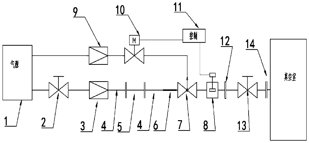
[0032] See attached figure 1 . A vacuum air intake system includes an air supply unit, a transmission unit, a control unit, and an air supply terminal;

[0033] The gas supply unit includes a gas source 1, a manual shut-off valve 2, a first pressure reducing valve 3 and corresponding connecting pipelines. The gas flows from the gas source 1 through the manual shut-off valve 2, and the first pressure reducing valve 3 enters after the pre...


PUM


Abstract

The invention discloses a vacuum air inlet system and an air inlet control method thereof. The vacuum air inlet system comprises an air supply unit, a transmission unit, a control unit and an air supply terminal, wherein the air supply unit comprises an air source, a manual stop valve, a pressure reducing valve and a corresponding connecting pipeline, and air enters the transmission unit from theair source through the manual stop valve and through adjusting corresponding pressure by the pressure reducing valve; the transmission unit comprises a transmission pipe, an insulating sleeve, a filter and a pneumatic valve; the control adjusting unit comprises a pressure reducing valve, an electromagnetic valve, a flow collector and a controller; and the air supply terminal comprises a vacuum adapter, a vacuum angle valve and a vacuum joint. The system is simple in composition and convenient to mount and dismount, and complex electronic instruments are not needed. A user can select an air source by himself or herself according to needs, and adaptability is high. The system is safe, stable and reliable in work, good in vacuum sealing performance, automatic in control, convenient and simpleto operate and capable of achieving automatic safe air inlet at any time.

Description

Technical field [0001] The invention relates to the field of vacuum and control, and mainly relates to a vacuum air intake system and an air intake control method. Background technique [0002] For a device in a high vacuum state, the pressure difference between inside and outside is very large. Due to maintenance, replacement of internal components, etc., the vacuum device must be opened. But before opening the device, vent the device first to make the pressure difference between the inside and outside consistent. Otherwise, opening the vacuum device rashly will not only damage the internal components, but also be dangerous to the operator, especially the large vacuum device. To release a vacuum, air is required. Taking into account factors such as economy and safety, nitrogen is injected into the vacuum chamber when vacuum is released. [0003] In addition, during the experiment, sometimes according to the needs of the experiment, it is necessary to inject air into the inside...

Claims


Application Information

Patent Timeline
Patent Type & Authority Applications(China)
IPC IPC(8): F04B41/02F04B37/14F04B39/10F04B39/16F04B49/06F04B39/14
CPCF04B41/02F04B37/14F04B39/10F04B39/16F04B49/06F04B39/14
Inventor 邑伟陶玲谢远来汪金新张照元唐宁张进新
Owner HEFEI INSTITUTES OF PHYSICAL SCIENCE - CHINESE ACAD OF SCI
Learn More