Distal locking nail sighting device for interlocking intramedullary nail

A technology of intramedullary nailing and distal locking, applied in the direction of internal fixator, fixator, internal bone synthesis, etc., can solve the problems such as the difficulty of locking the distal end of the intramedullary nail

Inactive Publication Date: 2019-01-18
熊海阔 +1
View PDF0 Cites 10 Cited by
  • Summary
  • Abstract
  • Description
  • Claims
  • Application Information

AI Technical Summary

Problems solved by technology

[0005] In view of the above defects in the prior art, the first object of the present invention is to provide a distal locking nail sight for interlocking intramedullary nails, which solves the problem of The difficulty of end-locking nails shortens the operation time and improves the operation efficiency

Method used


Image

  • Distal locking nail sighting device for interlocking intramedullary nail
  • Distal locking nail sighting device for interlocking intramedullary nail
  • Distal locking nail sighting device for interlocking intramedullary nail

Examples


Embodiment 1

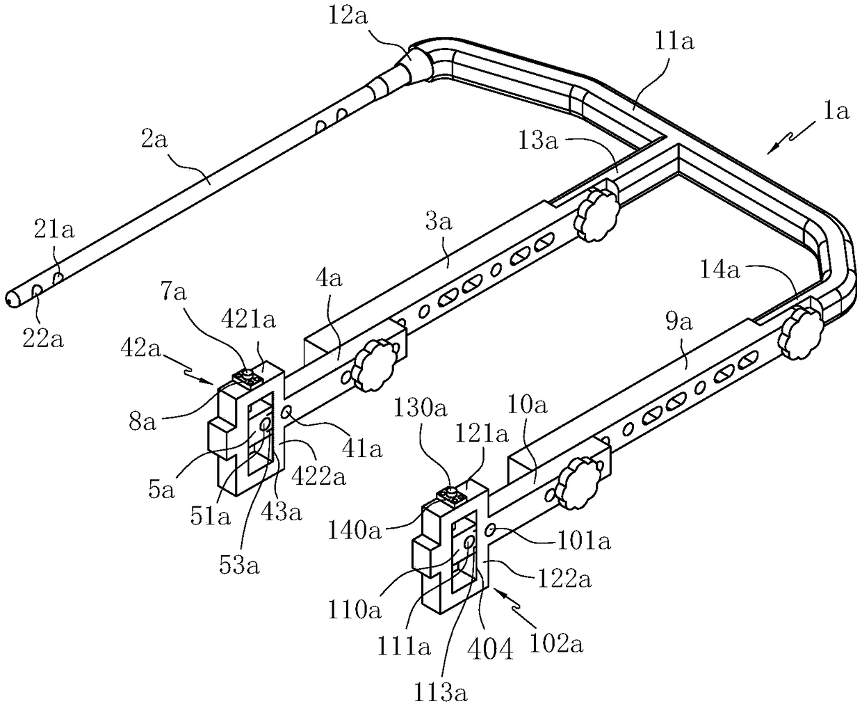
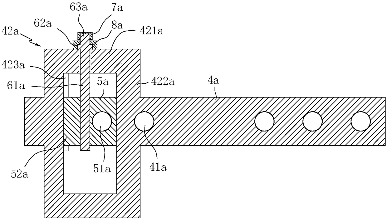
[0022] Such as Figure 1 to Figure 3 As shown together, a distal-end locking nail sight for interlocking intramedullary nails includes a handle 1a, a proximal guide rod 3a and a distal guide rod 4a, the handle 1a includes a handle body 11a, and the sides of the handle body 11a are arranged at intervals The first connecting rod 12a and the second connecting rod 13a, the first connecting rod 12a is tightly connected with the intramedullary nail 2a by bolts, the second connecting rod 13a is detachably connected with one end of the proximal guide rod 3a by a bolt, and the proximal guide rod 3a is detachably connected. The other end of bar 3a is detachably connected with far-end guide rod 4a by bolt, and far-end guide rod 4a is provided with guide slider installation frame 42a, and guide slider installation frame 42a is slidably provided with guide slider 5a, guide slider installation A first slider movement adjustment mechanism is provided between the frame 42a and the guide slide...

Embodiment 2

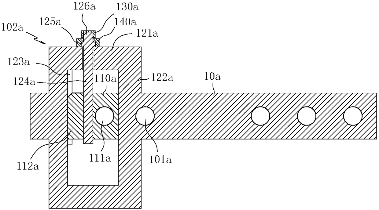
[0036] Such as Figure 4 to Figure 6 Commonly shown, its structure is basically the same as that of Embodiment 1, the difference is mainly reflected in the use of different handles 1b, the guide slider installation frame 42b is provided with a third connecting rod 14b, and the calibration slider installation frame 102b is provided with a third connecting rod 14b. Four connecting rods 9b, the third connecting rod 14b and the fourth connecting rod 9b are detachably connected by bolt fasteners. The detailed structure of this embodiment is as follows:

[0037] The handle 1b includes a handle body 11b, the side of the handle body 11b is provided with a first connecting rod 12b and a second connecting rod 13b at intervals, the first connecting rod 12b is tightly connected to the intramedullary nail 2b through a bolt, and the second connecting rod 13b is connected to the intramedullary nail 2b. One end of the near-end guide rod 3b is detachably connected by a bolt, and the other end...


PUM


Abstract

The invention discloses a distal locking nail sighting device for an interlocking intramedullary nail, and relates to the technical field of orthopaedic trauma medical instruments. A guide slider is slidably arranged in the guide slider mounting frame of the distal guide rod, Between that mount frame of the guide slider and the guide slider, a first slide movement adjusting mechanism is arranged,a distal guide rod is provided with a first guide hole, the guide slider is provided with a second guide hole, the upper and lower sides of the second guide hole are respectively provided with a firstmetal indicating line, and the side frame of the guide slider mounting frame is provided with a metal graduation line. The calibration slider mounting frame of the calibration lever is slidably provided with a calibration slider, a second slider movement adjusting mechanism is arranged between the calibration slider mounting frame and the calibrated slider, the calibration lever is provided witha first calibration hole, the calibration slider is provided with a second calibration hole, and the upper and lower sides of the second calibration hole are respectively provided with a second metalindicating line. The distal locking nail sighting device solves the problem that the distal end of the intramedullary nail is difficult to lock, shortens the operation time and improves the operationefficiency.

Description

technical field [0001] The invention relates to the technical field of orthopedic trauma medical devices, in particular to a distal locking nail aimer for interlocking intramedullary nails used for intramedullary fixation of fractures. Background technique [0002] The intramedullary nail is an orthopedic internal fixation device in the medical equipment. It is the first choice for internal fixation of femoral shaft fractures, and has unique advantages compared with steel plates. In use, in order to prevent the two parts of the fracture from rotating, it is necessary to use two screws to pass laterally through the femoral shaft and the intramedullary nail for locking. The doctor will use a drill guide to combine with the intramedullary nail before inserting the intramedullary nail into the bone marrow cavity. Together, theoretically, the guide hole of the guide is facing the locking screw hole of the intramedullary nail, so that the drill bit can pass through the guide hole...

Claims


Application Information

Patent Timeline
Patent Type & Authority Applications(China)
IPC IPC(8): A61B17/72A61B17/90
CPCA61B17/725A61B17/8897A61B17/90
Inventor 封亮亮熊海阔
Owner 熊海阔
Why Eureka
Try Eureka