A construction waste disposal device

A technology for processing equipment and construction waste, applied in grain processing, solid separation, chemical instruments and methods, etc., can solve problems such as unfavorable transportation and recycling, inability to guarantee crushing effect, uneven crushing effect, etc., and achieve fast and efficient processing. , to facilitate subsequent transportation, to ensure the effect of crushing effect

Active Publication Date: 2021-06-11
重庆市安平建筑有限责任公司
View PDF0 Cites 0 Cited by
  • Summary
  • Abstract
  • Description
  • Claims
  • Application Information

AI Technical Summary

Problems solved by technology

[0003] Most of the demolished construction waste exists in the form of blocks, which is inconvenient to transport and needs to be crushed. If it is to be recycled, it needs to be crushed to make it into particles before it can be used; the traditional crushing method is to manually use a drill or drive a drilling rig for crushing. The crushing effect is uneven, and the crushing effect cannot be guaranteed, which is not conducive to transportation and recycling

Method used


Image

  • A construction waste disposal device
  • A construction waste disposal device
  • A construction waste disposal device

Examples


Embodiment 1

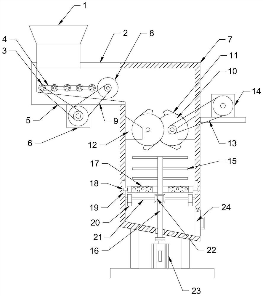
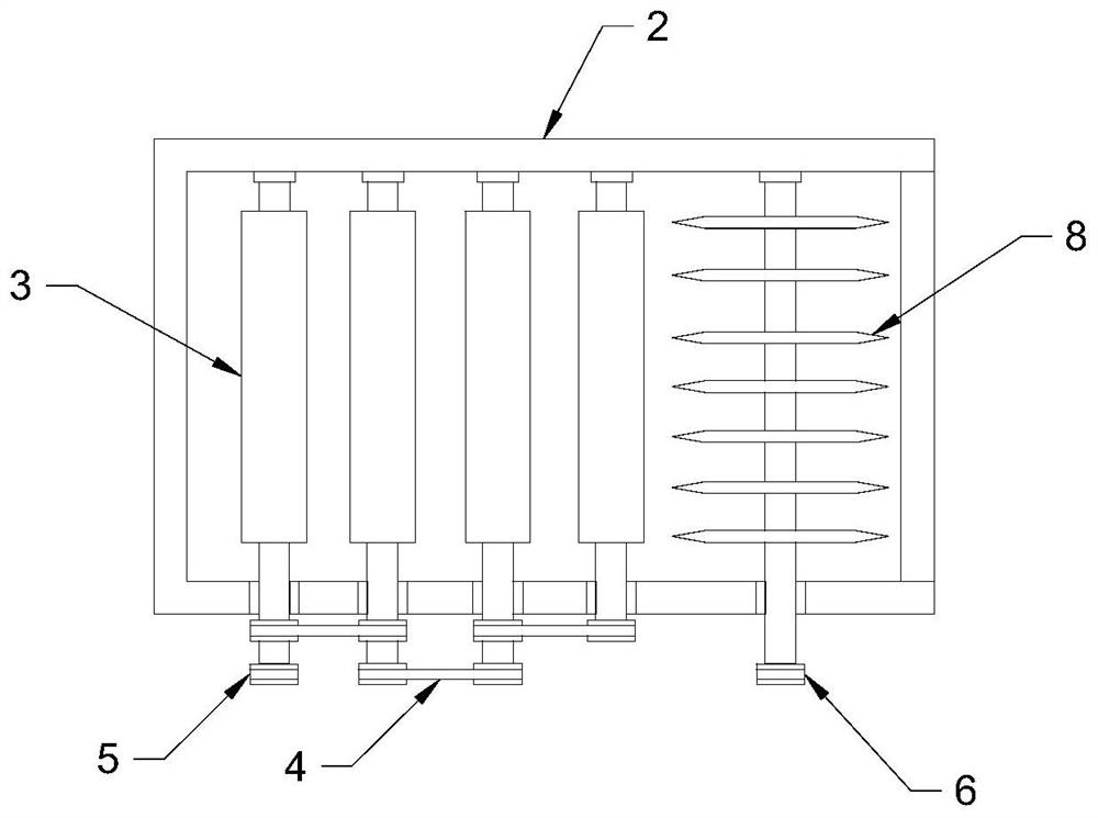
[0023] see Figure 1~3 , in an embodiment of the present invention, a construction waste treatment device includes a feeding hopper 1, a feeding box 2 and a crushing box 7; a feeding box 2 is communicated with the bottom of the feeding hopper 1, and an equidistant Distributed delivery rollers 3, the delivery rollers 3 are rotationally connected with the inner wall of the delivery box 2, the delivery rollers 3 are connected through the first transmission belt 4, and the delivery rollers 3 at the end are connected with the second transmission belt 5 An output shaft of the drive motor 6, the first drive motor 6 is fixedly connected with the lower end surface of the material delivery box 2 by means of bolts, and the first drive motor 6 drives the delivery roller 3 to rotate to transport the construction waste block.

[0024] The right side of the conveying box 2 is connected with a pulverizing box 7, and a cutting blade roller 8 is arranged at the communication place between the f...

Embodiment 2

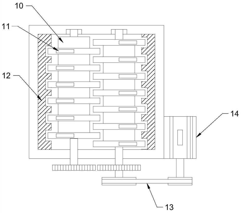
[0028] see Figure 4 The difference between this embodiment and Embodiment 1 is that: the inner wall of the upper end of the crushing box 7 is fixedly connected with a dust collection cover 25, the dust collection cover 25 is connected with an induced draft fan 26 through a pipeline, and the induced draft fan 26 is connected with a cyclone settling cylinder 27 through a pipeline , Actively absorb the dust in the crushing process to avoid dust overflow and pollute the working environment.


PUM


Abstract

The invention discloses a construction waste treatment device, which comprises a feeding hopper, a feeding box and a crushing box; a feeding box is connected under the feeding hopper, and feeding rollers distributed equidistantly are arranged in the feeding box, and the feeding box There is a crushing box connected to the right side, and a cutting blade roller is arranged at the connection between the conveying box and the crushing box; a squeezing roller set is arranged in the crushing box, a crushing knife is arranged under the squeezing roller set, and a sieve plate is arranged under the crushing knife , a cam abuts against the bottom of the sieve plate. The present invention cuts the construction waste blocks to be crushed by installing a cutting blade roller, separates the waste blocks, facilitates subsequent crushing, and improves the overall processing efficiency; by providing a sieve plate vibrating up and down under the crushing knife, the blockage of the sieve plate is avoided At the same time, the garbage blocks that have not reached the size of the crushing particle size are brought into contact with the crushing knife again to ensure the crushing effect; through the three-level mechanism of cutting, crushing and crushing, the waste blocks can be processed quickly and efficiently, which is convenient for subsequent transportation and recycling.

Description

technical field [0001] The invention relates to the construction field, in particular to a construction waste treatment device. Background technique [0002] Construction waste is solid waste generated during the process of new building, renovation, expansion or demolition of buildings. According to the different sources of construction waste, it can be divided into construction waste and demolition construction waste. Construction waste, as the name implies, is the solid waste generated in new construction, renovation or expansion projects, and demolition construction waste is the construction waste generated during the demolition of buildings. [0003] Most of the demolished construction waste exists in the form of blocks, which is inconvenient to transport and needs to be crushed. If it is to be recycled, it needs to be crushed to make it into particles before it can be used; the traditional crushing method is to manually use a drill or drive a drilling rig for crushing....

Claims


Application Information

Patent Timeline
Patent Type & Authority Patents(China)
IPC IPC(8): B02C4/08B02C18/12B02C23/16B07B1/34B26D1/28B26D7/06
CPCB02C4/08B02C18/0092B02C18/12B02C23/16B02C2023/165B02C2201/06B07B1/343B26D1/28B26D7/06
Inventor 渠衍飞
Owner 重庆市安平建筑有限责任公司
Why Eureka
Try Eureka