Pan-tilt for inspection robot of transformer substation

A technology for inspection robots and substations, applied in the field of pan/tilt, can solve problems such as difficult to meet high-precision requirements, limit robot usage scenarios, and low steering accuracy of pan/tilt, and achieve the effect of convenient design, simple structure, and convenient wiring

Inactive Publication Date: 2019-01-18
SHENZHEN LAUNCH DIGITAL TECH
View PDF10 Cites 6 Cited by
  • Summary
  • Abstract
  • Description
  • Claims
  • Application Information

AI Technical Summary

Problems solved by technology

[0002] In recent years, with the development of automation and artificial intelligence, intelligent inspection robot inspection systems for substations have been widely used. More and more PTZs are used, and the requirements for the accuracy of PTZs are also getting higher and higher. Traditional PTZs have low steering accuracy and have become It is difficult to meet the high-precision requirements. The traditional gimbal design has problems such as low positioning accuracy, complex structure, and unstable operation, which severely limits the use scenarios of robots.

Method used


Image

  • Pan-tilt for inspection robot of transformer substation
  • Pan-tilt for inspection robot of transformer substation
  • Pan-tilt for inspection robot of transformer substation

Examples


Embodiment 1

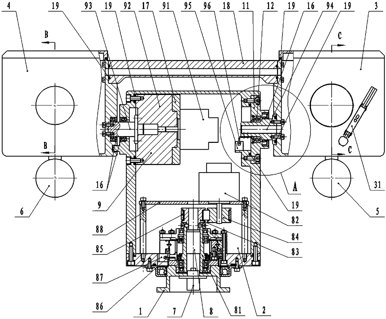
[0031] A substation inspection robot platform, comprising a fixed seat 1, a main cabin 2, a visible light camera cabin 3, an infrared camera cabin 4, a supplementary light 5 and a pickup 6, and the visible light camera cabin 3 and the infrared camera cabin 4 are respectively fixed On both sides opposite to the main cabin 2, and between the visible light camera cabin 3 and the infrared camera cabin 4, a connecting piece 18 is provided. Vertical drive mechanism 9;

[0032] A conductive slip ring 7 is fixedly installed in the fixed seat 1, and the horizontal driving mechanism 8 is fixed on the upper part of the conductive slip ring 7. The horizontal driving mechanism 8 includes a harmonic reducer I81 fixed on the bottom wall of the main cabin 2, Synchronous wheel I 83, synchronous wheel II 84, synchronous belt 85 and servo motor I 82 with encoder, said harmonic reducer I 81 output end slot is fixed with photoelectric switch trigger I 86, installed on the bottom wall of main cabin...

Embodiment 2

[0038] On the basis of Embodiment 1, the output end of the harmonic reducer I81 is connected to the fixed seat 1, and the input end is connected to the synchronous wheel I83. The synchronous wheel I83 is connected to the synchronous wheel II84 through the synchronous belt 85. The synchronous wheel II84 is fixedly connected with the output shaft of the servo motor I82 with an encoder, the servo motor I82 with an encoder is installed on the motor mounting frame 88, and the harmonic reducer I81 is a hollow type reducer, which is convenient for internal use The cable is routed, and the inner hole of the synchronous wheel II84 is coaxially fixedly connected with the output shaft of the servo motor I82 with an encoder, which can ensure that the inner hole of the synchronous wheel II84 rotates synchronously with the output shaft of the servo motor I82 with an encoder. The synchronous wheel Ⅰ83 and synchronous wheel Ⅱ84 have the same number of teeth to ensure synchronous rotation. The ...

Embodiment 3

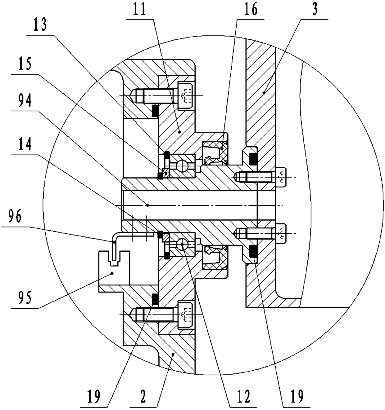
[0040] On the basis of Embodiment 1, one end of the passive shaft 94 is fixedly connected to the visible light camera cabin 3, and the other end is bearing-connected to the main cabin 2. The main cabin 2 is provided with a bearing seat 11, and the bearing seat 11 is provided with Bearing 12, a circlip 13 for the hole and a circlip 14 for the shaft, a shaft shoulder retaining ring 15 is installed on the outer cylindrical surface of the driven shaft 94, and the right end surface of the shoulder retaining ring 15 is tightly connected to the left end surface of the inner ring of the bearing 12. The circlip 13 for the hole is installed in the groove processed by the bearing seat 11 for the axial limit of the outer ring of the bearing 12, and the circlip 14 for the shaft is installed in the groove processed by the driven shaft 94 for the shaft shoulder The stop ring 15 and the axial limit of the inner ring of the bearing 12.


PUM


Abstract

The invention discloses a pan-tilt for an inspection robot of a transformer substation. The pan-tilt comprises a fixing base, a main cabin, a visible light camera cabin, an infrared camera cabin, a fill-in light lamp and a pickup. A connector is arranged between the visible light camera cabin and the infrared camera cabin, a horizontal driving mechanism for driving the pan-tilt to rotate horizontally and a vertical driving mechanism for driving the pan-tilt to rotate vertically are arranged in the main cabin, and an electric conduction slide ring is installed in the fixing base; the horizontaldriving mechanism is fixed to the upper portion of the electric conduction slide ring and comprises a harmonic reducer I, a synchronous wheel I, a second synchronous wheel II, a synchronous belt anda servo motor I with a coder, and the harmonic reducer I, the synchronous wheel I, the second synchronous wheel II, the synchronous belt and the servo motor I with the coder are fixed to the bottom wall of the main cabin; the vertical driving mechanism comprises a servo motor II with a coder, a harmonic reducer II, an active shaft and a passive shaft, and an optoelectronic switch trigger part andan optoelectronic detection switch are arranged in the horizontal driving mechanism and the vertical driving mechanism respectively. The pan-tilt has high repeat positioning precision and is high in stability and protection level, simple in structure and convenient to design.

Description

technical field [0001] The invention relates to the field of cloud platform technology, in particular to a platform for a substation inspection robot. Background technique [0002] In recent years, with the development of automation and artificial intelligence, intelligent inspection robot inspection systems for substations have been widely used. More and more PTZs are used, and the requirements for the accuracy of PTZs are also getting higher and higher. Traditional PTZs have low steering accuracy and have become It is difficult to meet the high-precision requirements. The traditional gimbal design has problems such as low positioning accuracy, complex structure, and unstable operation, which severely limits the use scenarios of robots. Contents of the invention [0003] The object of the present invention is to provide a platform for a substation inspection robot, which has high repeat positioning accuracy, high stability and protection level, simple structure and conven...

Claims


Application Information

Patent Timeline
Patent Type & Authority Applications(China)
IPC IPC(8): B25J19/00
CPCB25J19/00
Inventor 肖声敬高磊
Owner SHENZHEN LAUNCH DIGITAL TECH
Why Eureka
Try Eureka