Lifting type wall grooving machine

A slotting machine and lift-type technology, which is applied in the field of lift-type wall slotting machines, can solve the problems of unfavorable staff working normally, high labor intensity, and low efficiency, so as to improve the quality of wall painting, improve work efficiency, and reduce The effect of labor intensity

Inactive Publication Date: 2019-01-18
浙江众亿智能科技有限公司
View PDF5 Cites 5 Cited by
  • Summary
  • Abstract
  • Description
  • Claims
  • Application Information

AI Technical Summary

Problems solved by technology

If the traditional manual excavation is adopted, the grooves on the wall must be cut out first, and then the wire grooves should be cut out with an electric hammer. This method is complicated to operate, inefficient, and causes great damage to the wall. It is not only labor-intensive, but also time-consuming.
The wall slotting machine was born as the times require. This product belongs to electric tools. The traditional wall slotting machine is mainly composed of a fuselage, a motor, a motor casing, a gear box, a bracket, a switch box, a knife cover, a gear pair, The output shaft, cutter and handle are combined, but this kind of wall slotting machine has great limitations. The slotting machine is very inconvenient to use; in addition, it will cause a lot of dust when slotting, which will seriously pollute the environment on the job site and is not conducive to the normal work of the staff.

Method used


Image

  • Lifting type wall grooving machine
  • Lifting type wall grooving machine
  • Lifting type wall grooving machine

Examples


Embodiment Construction

[0032] Below in conjunction with accompanying drawing and embodiment of description, specific embodiment of the present invention is described in further detail:

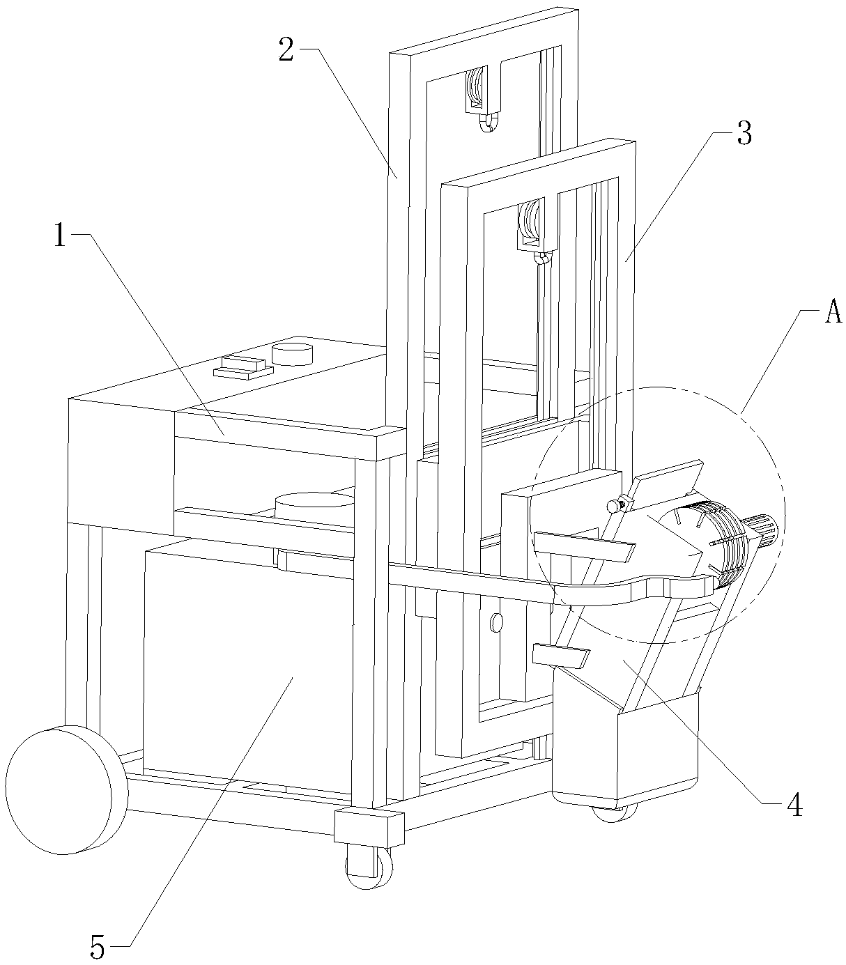
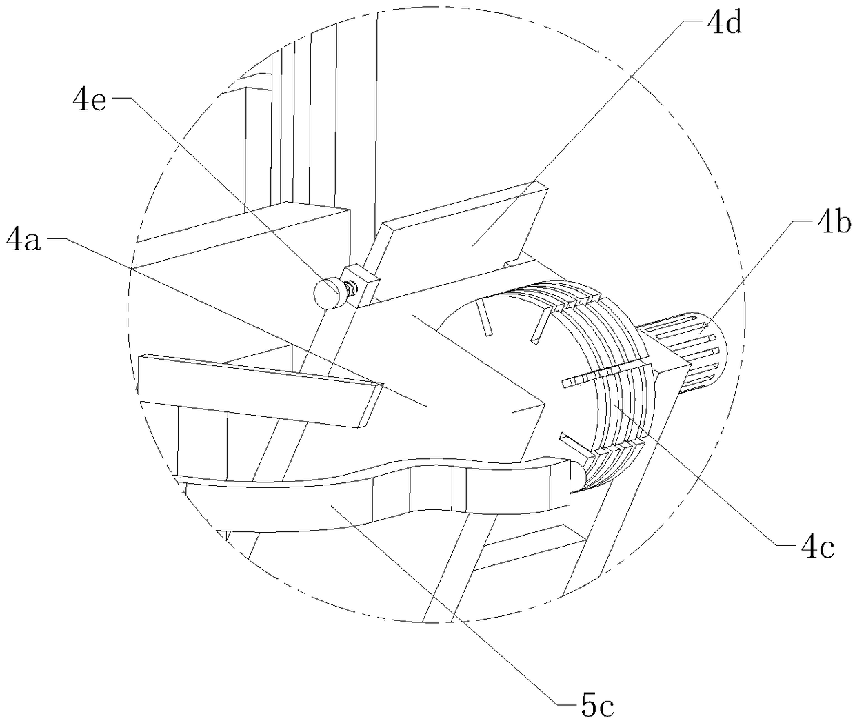
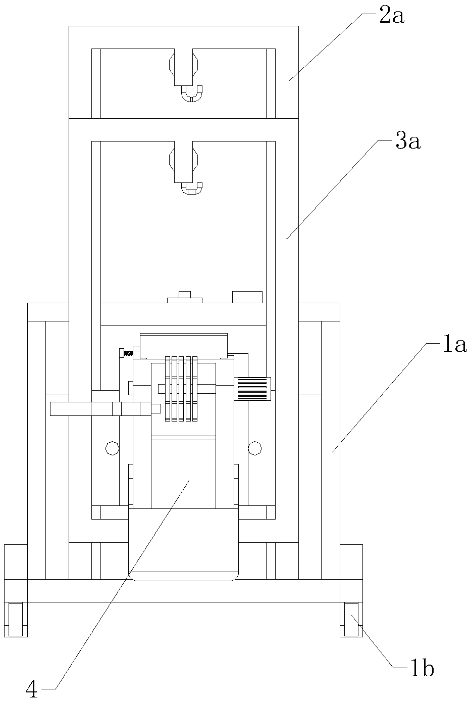
[0033] refer to Figure 1 to Figure 16A lifting type wall slotting machine shown includes a body body 1, a first lifting frame 2, a second lifting frame 3, a slotting device 4 and a flushing device 5, and the body body 1 includes a vehicle frame 1a, a wheel assembly 1b and a control box 1c, the wheel assembly 1b is arranged under the vehicle frame 1a, the control box 1c is arranged on the vehicle frame 1a, the first lifting frame 2 is a rectangular frame structure, and the first lifting frame 2 includes There are a first fixed frame 2a, a first pulley block and a first movable plate 2c, the first fixed frame 2a is arranged in front of the vehicle frame 1a, the first pulley block is arranged on the first fixed frame 2a, and the first movable plate The plate 2c is arranged on the first fixed frame 2a, the first pulle...


PUM


Abstract

The invention relates to the field of architecture home decoration equipment, in particular to a lifting type wall grooving machine. The lifting type wall grooving machine comprises a vehicle body, afirst lifting frame, a second lifting frame, a grooving device and a flushing device. The first lifting frame comprises a first fixed frame, a first pulley set and a first movable plate, a steering assembly is arranged on the first movable plate, and the second lifting frame comprises a second fixed frame, a second pulley set and a second movable plate. A first rotary handle is rotated to drive afirst transmission wheel to rotate, so that the first pulley set operates, the first movable plate is driven to longitudinally move, then the second lifting frame and the grooving device are driven tovertically move, and longitudinal grooving of a wall is completed. By rotating the second lifting frame, the second lifting frame can rotate through a steering shaft, the grooving device can also rotate accordingly, a second rotary handle is rotated to drive a second transmission wheel to rotate, the second pulley set operates, and the second movable plate is driven to move left and right. The lifting type wall grooving machine is easy to operate and high in efficiency, and wall grooving can be omnibearingly carried out at multiple angles.

Description

technical field [0001] The invention relates to the field of construction and home improvement equipment, in particular to a lifting type wall slotting machine. Background technique [0002] In order to make the home environment more beautiful, most families now make grooves on the wall when they are decorating. Sealing ensures the aesthetics of the building as a whole. If the traditional manual excavation is adopted, the grooves on the wall must be cut out first, and then the wire grooves should be cut out with an electric hammer. This method is complicated to operate, inefficient, and causes great damage to the wall. It is not only labor-intensive, but also time-consuming. The wall slotting machine was born as the times require. This product belongs to electric tools. The traditional wall slotting machine is mainly composed of a fuselage, a motor, a motor casing, a gear box, a bracket, a switch box, a knife cover, a gear pair, The output shaft, cutter and handle are comb...

Claims


Application Information

Patent Timeline
IPC IPC(8): B28D1/04B28D7/00B28D7/02
CPCB28D1/045B28D1/048B28D7/00B28D7/02
Inventor 史敏达石士旭陈晔史音棋石筱菀
Owner 浙江众亿智能科技有限公司
Why Eureka
Try Eureka