
Injection mold for router base and injection process of router base

A technology for injection molds and routers, applied in the direction of coating, etc., can solve the problems of prolonging injection molding time, long cooling molding time, uneven mixing, etc., to ensure quality, reduce molding cycle and production costs, and ensure aesthetics and quality Effect

Inactive Publication Date: 2019-01-18
昆山弘正电子科技有限公司
View PDF8 Cites 0 Cited by
  • Summary
  • Abstract
  • Description
  • Claims
  • Application Information

AI Technical Summary

Problems solved by technology

[0004] Chinese Patent Publication No. CN 207344999 U discloses a kind of injection mold. Since the filling nozzle is completely accommodated in the upper template and the upper mold core, the size of the filling nozzle is smaller and the length of the runner is shorter, which shortens the injection molding process. It shortens the time that the flow material stays in the flow channel, which is beneficial to product molding and improves production efficiency. However, due to certain differences in the fluidity and temperature of the flow material, there is uneven mixing during mixing, and bonding lines will appear after entering the cavity for molding and cooling. , and the cooling molding time of the product is longer, which greatly prolongs the injection molding time and increases the production cost

Method used


Image

  • Injection mold for router base and injection process of router base
  • Injection mold for router base and injection process of router base
  • Injection mold for router base and injection process of router base

Examples


Embodiment

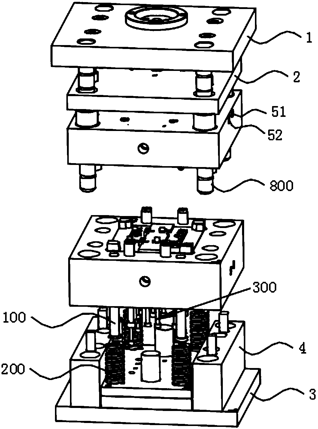
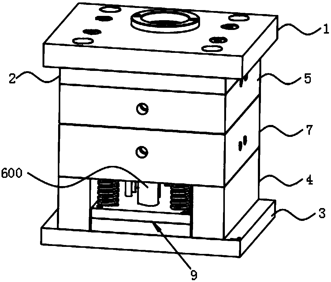
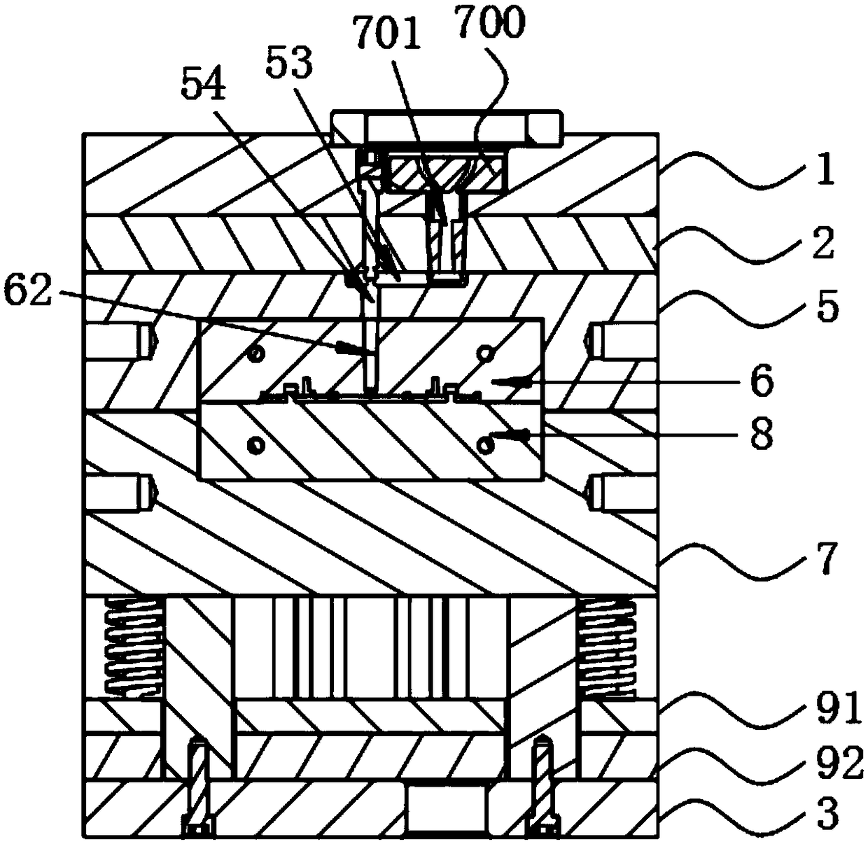
[0060] Embodiment: a kind of injection mold of router base, such as Figure 1-Figure 7 As shown, it includes a panel 1, a nozzle plate 2, a female module, a male module and a bottom plate 3, the nozzle plate 2 is located between the panel 1 and the female module, and the bottom plate 3 is provided with two die feet 4, The male module is fixed on the die foot 4;

[0061] The female module includes a female template 5 and a female mold core 6, the female template 5 is provided with the female mold core 6 near the surface of the male module, and the male module includes a male template 7 and a male mold core 8, so The surface of the male module close to the female module is provided with a male mold core 8, and a mold cavity is formed between the female mold core 6 and the male mold core 8;

[0062] The side wall of the master template 5 is provided with a master mold water inlet 51 and a master mold water outlet 52, and the master mold water inlet 51 and the master mold water o...


PUM


Abstract

The invention discloses an injection mold for a router base and an injection process of the router base. The injection mold comprises a panel, a striper plate, a female module, a male module and a bottom plate, wherein the striper plate is positioned between the panel and the female module; two pins are arranged at the bottom plate; the male module is fixed at the pins; the panel is provided witha sprue bush; a sprue runner is arranged inside the sprue bush, and comprises an inlet runner, a mixing cavity and an outlet runner; glue inlet runners are communicated with the mixing cavity; the mixing cavity is communicated with the outlet runner; fluid inlets of a plurality of glue inlet runners are formed in the upper end face of the sprue bush; and the glue inlet runners are symmetrically arranged in a pairwise manner. According to the cooling runner having a zigzag structure, the cooling efficiency is improved, the whole injection molding cycle is reduced, the fluids can be mixed more uniformly, binding lines formed on a product among different fluids can be avoided, and the injection product quality and surface appearance of an injection product can be ensured.

Description

technical field [0001] The invention belongs to the technical field of moulds, in particular to an injection mold for a router base. Background technique [0002] Injection molding, also known as injection molding, is a molding method of injection and molding. The advantages of the injection molding method are fast production speed, high efficiency, automatic operation, many varieties of designs and colors, shapes from simple to complex, sizes from large to small, and accurate product sizes, which can form complex-shaped parts. Injection molding It is suitable for mass production of products with complex shapes and high production efficiency. [0003] Injection molding technology is to add granular or powdery polymer raw materials into the polymer barrel, plasticize under heating or mechanical shearing, and finally enter the mold under the push of a plunger or screw, and cool and solidify to form a mold cavity. Consistent polymer articles. [0004] Chinese Patent Publicat...

Claims


Application Information

Patent Timeline
Patent Type & Authority Applications(China)
IPC IPC(8): B29C45/73B29C45/27B29C45/26B29C45/00
CPCB29C45/0025B29C45/2602B29C45/27B29C45/7312
Inventor 钟健
Owner 昆山弘正电子科技有限公司
Learn More