Cam-driven-type multi-station press transmission system

A multi-station press and transmission system technology, applied in the field of presses, can solve the problems of large assembly gap and poor machining accuracy of workpieces, and achieve the effect of eliminating assembly gaps

Pending Publication Date: 2019-01-18
扬州精善达伺服成形装备有限公司
View PDF1 Cites 4 Cited by
  • Summary
  • Abstract
  • Description
  • Claims
  • Application Information

AI Technical Summary

Problems solved by technology

[0007] The purpose of the present invention is to provide a cam-driven multi-station press transmission system, which solves the technical problems of large assembly gaps and poor machining accuracy of workpieces in the prior art

Method used


Image

  • Cam-driven-type multi-station press transmission system
  • Cam-driven-type multi-station press transmission system
  • Cam-driven-type multi-station press transmission system

Examples


Embodiment

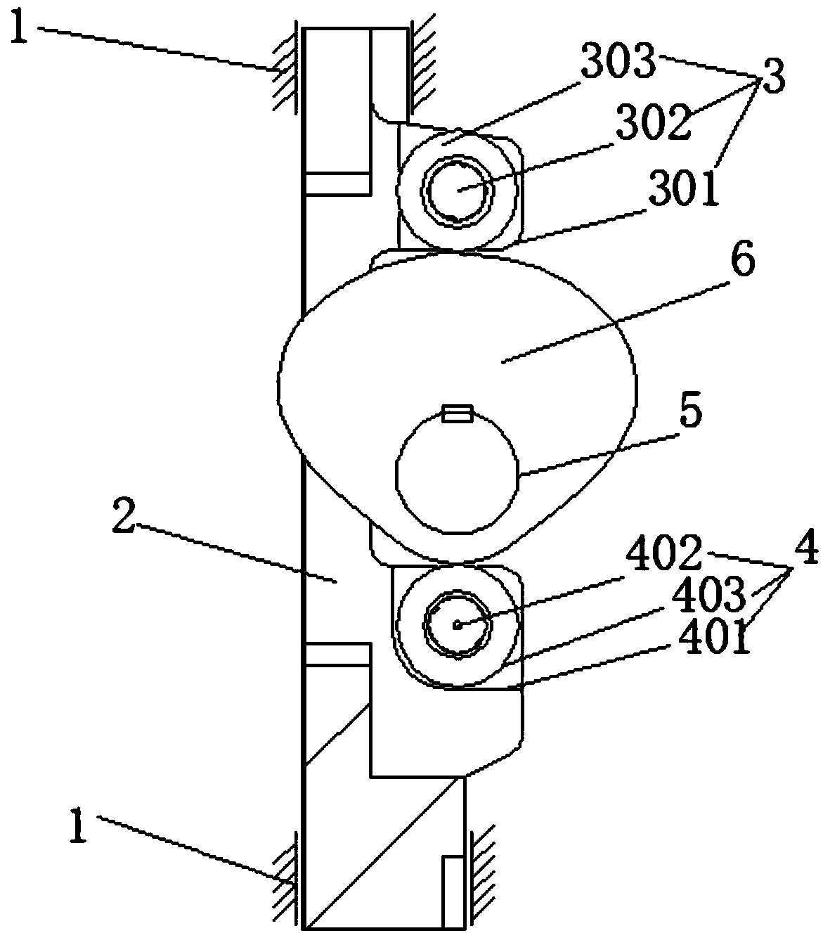
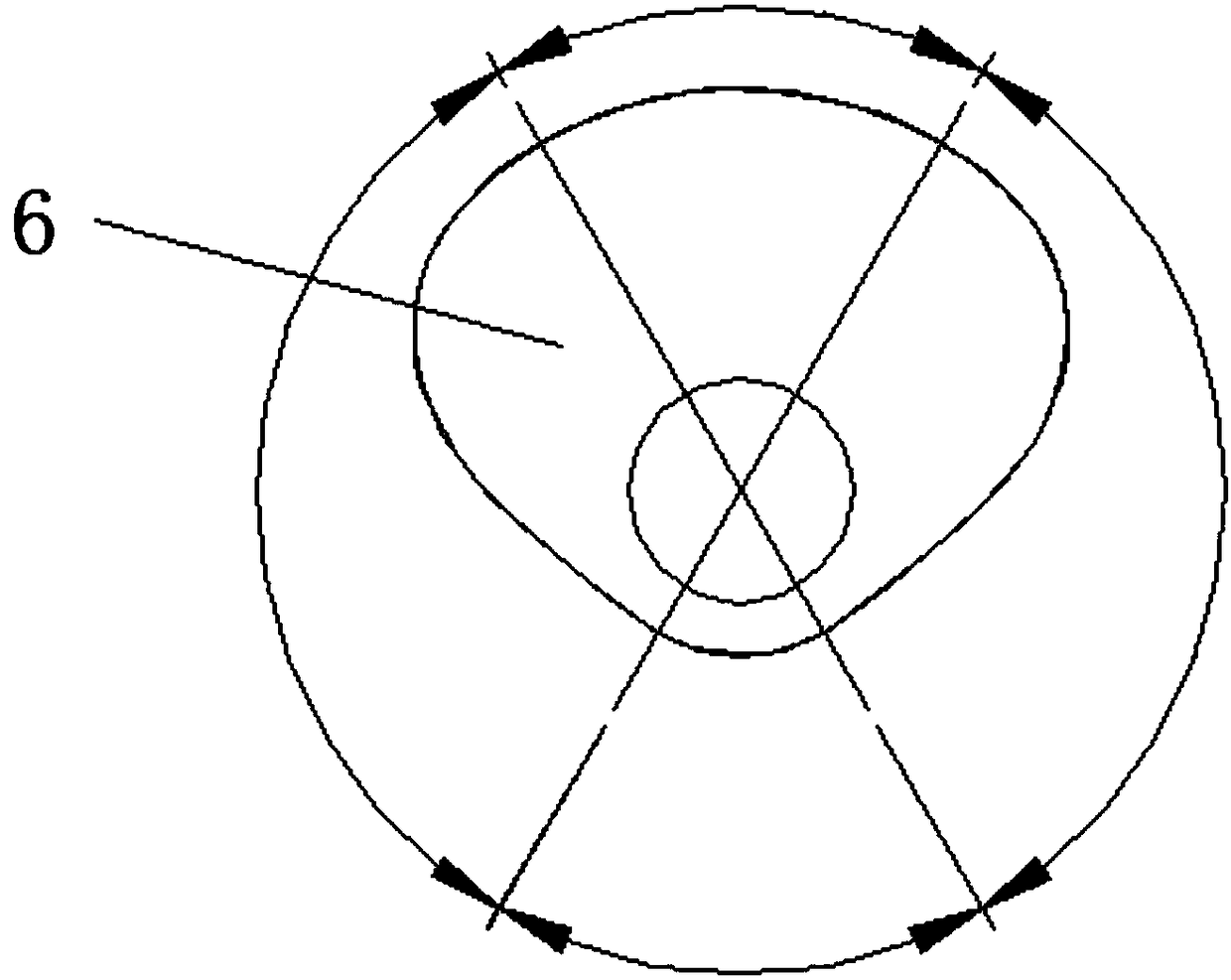
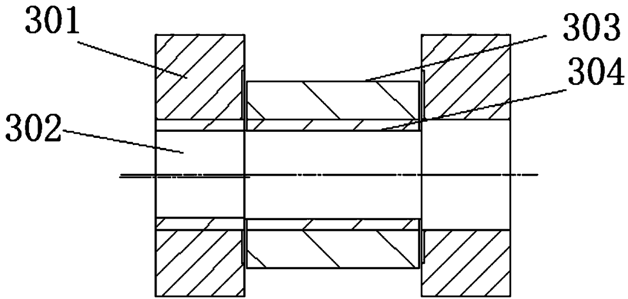
[0030] Such as Figure 1-2 As shown, a cam-driven multi-station press transmission system provided by the present invention includes a frame 1, a slider 2 and a main shaft 5, the slider 2 is slidably mounted on the frame 1, and the slider 2 The upper roller mechanism 3 and the lower roller mechanism 4 are installed at intervals, the main shaft 5 is installed on the frame 1, and the main cam 6 is installed on the main shaft 5, and the main shaft 5 is located at the upper roller mechanism 3 and the lower roller mechanism. 4, the main cam 6 is tangent to the upper roller mechanism 3 and the lower roller mechanism 4 respectively; the main shaft 5 and the main cam 6 in the present invention are used as power sources, and by promoting the upper roller mechanism 3 and the lower roller mechanism 4, it can The slider 2 moves up and down to realize the linear motion of the slider.

[0031] Wherein, the main shaft 5 is interference fit with the main cam 6, and the center of rotation of ...


PUM


Abstract

The invention discloses a cam-driven-type multi-station press transmission system. The system comprises a rack, a slide block and a main shaft; the slide block is slidably installed on the rack, and an upper idle wheel mechanism and a lower idler wheel mechanism are spaced on the slide block; the main shaft is installed on the rack, a main cam is installed on the main shaft, the main shaft is located between the upper idler wheel mechanism and the lower idler wheel mechanism, and the main cam is tangent to the upper idler wheel mechanism and the lower idler wheel mechanism separately. By meansof the system, the technical problem in the prior art that the processing precision of workpieces is poor when large assembly gaps exist in a station press is solved.

Description

technical field [0001] The invention relates to the technical field of presses, in particular to a transmission system of a cam-driven multi-station press. Background technique [0002] The main transmission system of the traditional crank-link drive multi-station press is mainly composed of cranks, connecting rods, sliders and other parts. When working, the crank rotates and makes a circular motion; the crank drives the connecting rod, and the connecting rod drives the slider to make a reciprocating linear motion. [0003] The disadvantages of traditional crank-connecting rod-driven multi-station presses are as follows: [0004] (1) There are copper sleeves between the crank and the connecting rod, between the connecting rod and the slider, and a large assembly gap needs to be reserved to prevent the parts from locking during work; because there are many assembly gaps and they are accumulated step by step , when reaching the level of the slider, the gap is already very la...

Claims


Application Information

Patent Timeline
Patent Type & Authority Applications(China)
IPC IPC(8): B30B1/26
CPCB30B1/261B30B1/266
Inventor 严惠
Owner 扬州精善达伺服成形装备有限公司
Why Eureka
Try Eureka