
Novel configuration vertical take-off and landing unmanned aerial vehicle and flight control method thereof

A technology for vertical take-off and landing, unmanned aerial vehicle, applied in vertical take-off and landing aircraft, aircraft control, aircraft and other directions, can solve the problems of poor aircraft stability and maneuverability, low degree of realization, low flight efficiency of aircraft, etc. Military and civilian prospects, delayed airflow separation, the effect of a simple body structure

Pending Publication Date: 2019-01-18
NANJING UNIV OF AERONAUTICS & ASTRONAUTICS
View PDF9 Cites 3 Cited by
  • Summary
  • Abstract
  • Description
  • Claims
  • Application Information

AI Technical Summary

Problems solved by technology

[0004] The patent CN 202481313U applied by Tang Jiwei from Northwestern Polytechnical University and others proposes a flying-wing aircraft equipped with cycloidal propellers. The cycloidal propellers of the aircraft are installed above the flying-wing layout body along the symmetry plane of the flying-wing layout body. , and the movement of the propeller blades of the cycloidal propeller is outside the upper surface of the flying wing layout, and a control mechanism is used to realize the vertical take-off and landing or forward flight of the aircraft, but the flight efficiency of the aircraft is low, and the omega vortex generated by the cycloidal propeller The spin and the body form a strong induced interference, the stability and maneuverability of the aircraft are not good, and the degree of realization is low

Method used


Image

  • Novel configuration vertical take-off and landing unmanned aerial vehicle and flight control method thereof
  • Novel configuration vertical take-off and landing unmanned aerial vehicle and flight control method thereof
  • Novel configuration vertical take-off and landing unmanned aerial vehicle and flight control method thereof

Examples


Embodiment Construction

[0041] In order to make the object, technical solution and effect of the present invention clearer and clearer, the following examples are given to further describe the present invention in detail. It should be pointed out that the specific implementations described here are only used to explain the present invention, not to limit the present invention.

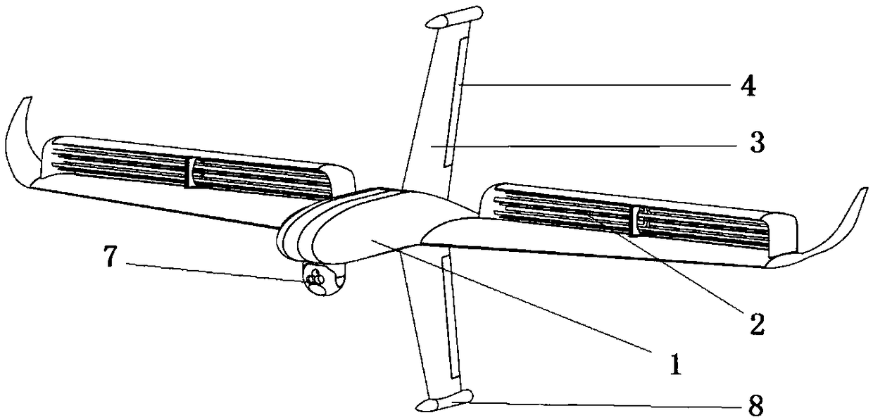
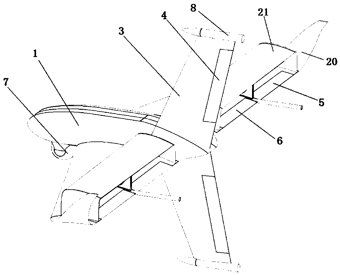
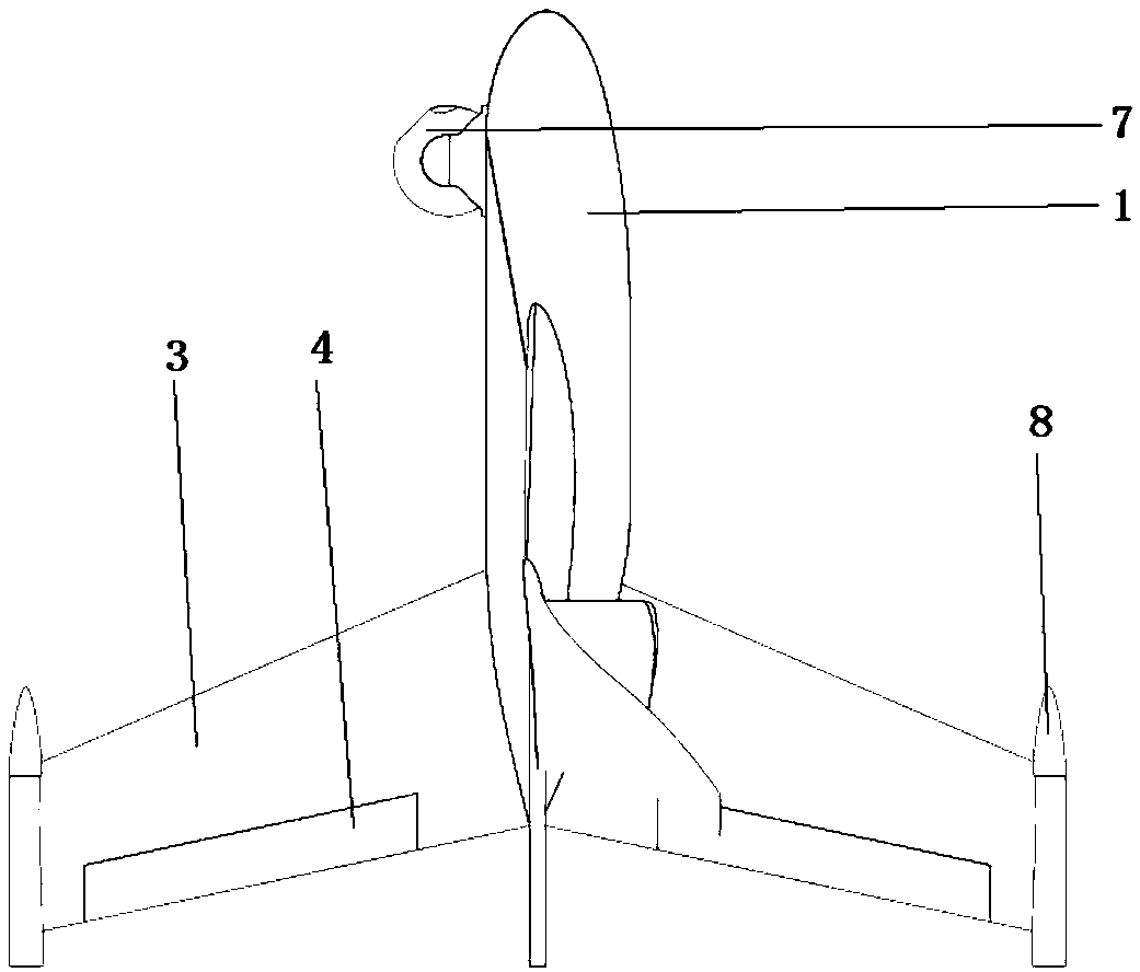
[0042] like Figure 1~2 As shown, a new configuration vertical take-off and landing UAV of the present invention includes a fuselage 1, a rolling wing system 2, a vertical tail 3, a rudder 4, an aileron 5, a flap 6, a reconnaissance pod 7 and a landing actuator 8.

[0043] Wherein, the described wing comprises left and right secondary main wings 20 and a winglet 21 above the main wing, and a rolling system 2 is installed in the duct formed by the main wing 20 and the winglet 21, and the rolling system 2 consists of The left and right groups of four sections are composed of rollers with the same size and opposite rotation; t...


PUM


Abstract

The invention discloses a novel configuration vertical take-off and landing unmanned aerial vehicle belonging to the field of aircraft transmission system and lifting rotor, which comprises a fuselage, a rolling wing system, a vertical tail, a rudder, an aileron, a flap, a detection pod and an take-off and landing actuating cylinder. A rolling wing system is installed in the duct of the wing, andthe rolling wing system is composed of two groups of rolling wings with the same size and opposite rotating directions. The propeller shaft of each roller section is coaxial, and the full vector propulsion system of cycloidal propeller is composed of two sections of each group. The invention discloses a novel configuration vertical take-off and landing unmanned aerial vehicle, which can realize vertical take-off and landing on land-based platform and sea-based platform, and has better flying quality. The invention combines the characteristics of a rotor aircraft and a fixed-wing aircraft, andhas low dependence on take-off and landing site and strong environmental adaptability. At the same time, the whole structure of cycloidal propeller system is light and simple, which has broad militaryand civilian prospects.

Description

technical field [0001] The invention relates to a general aviation aircraft, relates to the field of aircraft transmission system and lift rotor, in particular to a new configuration vertical take-off and landing unmanned aerial vehicle. Background technique [0002] At present, the aircraft capable of vertical take-off and landing are mainly rotor-type aircraft, but the rotor-type aircraft has obvious disadvantages such as low efficiency, high noise, cumbersome manipulation, complex mechanism, and low forward flight speed. This type of aircraft is small and can fly forward at a high speed during forward flight, but fixed-wing aircraft cannot achieve vertical take-off and landing, and is highly dependent on the take-off and landing site, so both are subject to certain restrictions in use; currently The aircraft that can realize vertical take-off and landing and high-speed forward flight at the same time is mainly the tilt-rotor aircraft, but the tilt-rotor aircraft not only ...

Claims


Application Information

Patent Timeline
Patent Type & Authority Applications(China)
IPC IPC(8): B64C29/00B64C3/38B64C3/36B64C5/06
CPCB64C3/36B64C3/38B64C5/06B64C29/0008
Inventor 曾嘉楠朱清华申遂愿朱振华丁正原
Owner NANJING UNIV OF AERONAUTICS & ASTRONAUTICS
Learn More