Wafer film sticking mechanism

A film sticking mechanism, the technology of the original film, applied in packaging and other directions, can solve the problem of easy wear and tear of the original film, and achieve the effect of ensuring quality, preventing wear, and preventing movement

Inactive Publication Date: 2019-01-18
重庆市嘉凌新科技有限公司
View PDF4 Cites 4 Cited by
  • Summary
  • Abstract
  • Description
  • Claims
  • Application Information

AI Technical Summary

Problems solved by technology

[0005] The present invention intends to provide an original film sticking mechanism to solve the problem that the original film is easy to wear in the prior art

Method used


Image

  • Wafer film sticking mechanism
  • Wafer film sticking mechanism

Examples


Embodiment Construction

[0021] The following is further described in detail through specific implementation methods:

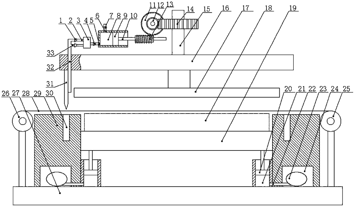
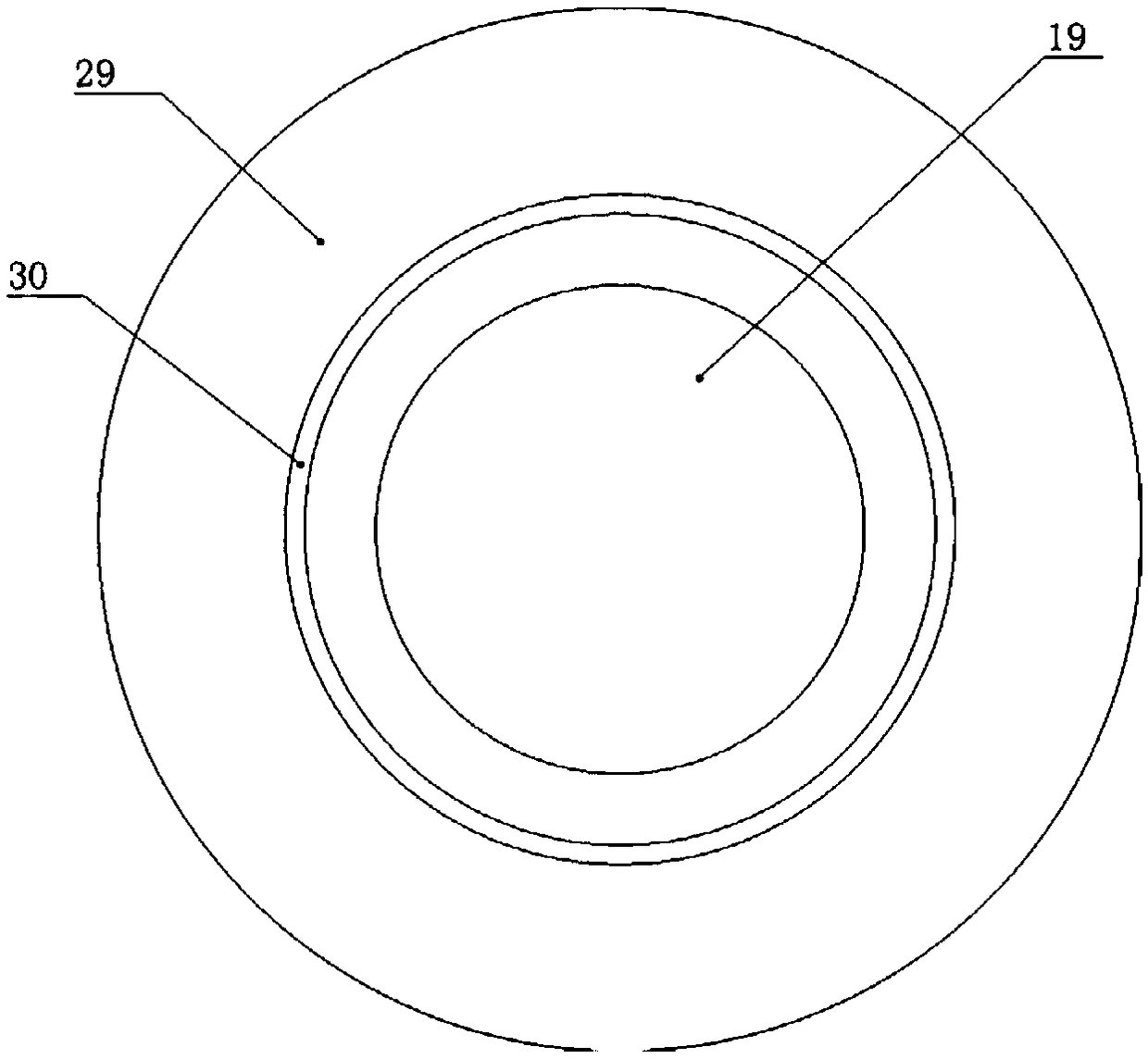
[0022] The reference signs in the drawings of the description include: valve 1, hot gas pipe 2, vortex tube 3, one-way outlet valve 4, outlet pipe 5, intake pipe 6, one-way inlet valve 7, pump 8, pump piston 9, Piston rod 10, transmission gear 11, driving screw 12, transmission screw 13, driving gear 14, rotating shaft 15, turntable 16, pressure plate 17, original sheet 18, support plate 19, buffer piston 20, sleeve 21, conduit 22, Air bag 23, cavity 24, receiving roller 25, feeding roller 26, base 27, film belt 28, processing table 29, cutting hole 30, cutter 31, nozzle pipe 32, air-conditioning pipe 33.

[0023] The embodiment is basically as attached figure 1 Shown:

[0024] The film pasting mechanism of the original film of the present invention comprises a frame, on which a base 27 is slidably installed, and a cylinder is installed on the frame, and the cylinder is connected w...


PUM


Abstract

The invention relates to the technical field of chip processing, in particular to a wafer film sticking mechanism. The mechanism comprises a sliding base, a processing table is arranged on the base, and the two sides of the processing table are provided with a feeding roller and a receiving roller respectively; a thin film strip is tensioned on the feeding roller and the receiving roller, a roundsupporting plate used for containing a wafer is arranged in the processing table, and an annular cutting hole is formed in the processing table; the circle center of the cutting hole coincides with the circle center of the supporting plate, and the diameter of the cutting hole is larger than that of the supporting plate; a turntable is arranged above the processing table, and the turntable is connected with a driving mechanism used for driving the turntable to rotate; a pressing plate is arranged below the rotating disc, a cutter is arranged at the bottom of the rotating disc, and the cutter is intermittently inserted into the cutting hole. According to the mechanism, the problem that in the prior art, the wafer is easy to abrade is solved.

Description

technical field [0001] The invention relates to the technical field of chip processing, in particular to an original film sticking mechanism. Background technique [0002] Wafer is the raw material for chip production, which refers to the silicon wafer used in the production of silicon semiconductor integrated circuits. Because of its circular shape, it is called a wafer, and it is also called the original chip in the actual application process. [0003] Various circuit element structures can be processed on the original sheet. Usually, the side with the circuit element structure is called the front side, and the other side is called the back side. During the processing of the original sheet, the front side needs to be covered with a film to prevent circuit components from being damaged. . In the prior art, the original film is often covered by the original film laminating machine. By placing the original film on the bottom plate, the film is covered on the original film, t...

Claims


Application Information

Patent Timeline
Patent Type & Authority Applications(China)
IPC IPC(8): B65B61/08
CPCB65B61/08
Inventor 罗云红
Owner 重庆市嘉凌新科技有限公司
Why Eureka
Try Eureka