Buffer mechanism and sorting system
A buffer mechanism, sponge board technology, applied in sorting, conveyor, transportation and packaging, etc., can solve the problem of easy crash and other problems, and achieve the effect of increasing the buffer effect.
- Summary
- Abstract
- Description
- Claims
- Application Information
AI Technical Summary
Problems solved by technology
Method used
Image
Examples
example 1
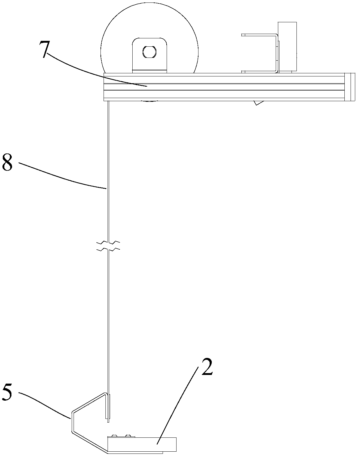
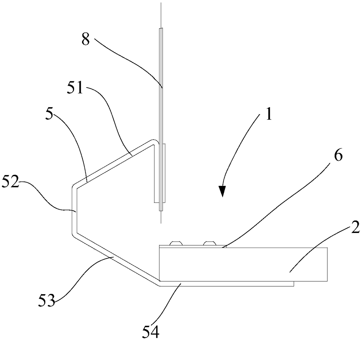
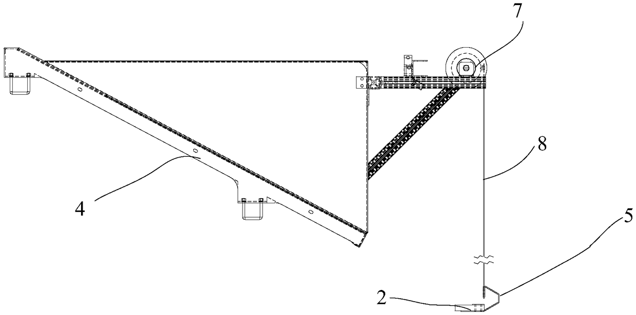
[0058] Example 1: If figure 2 As shown, the shaped bar 5 includes a first rod 51 , a second rod 52 , a third rod 53 and a fourth rod 54 . On the same plane, one end of the first rod 51 is connected to the second rod 52, and the other end of the third rod 53 is connected to the second rod 52, while the first rod 51 and the third rod 53 face away from the side of the sponge board 2. extend. The first bar 51, the second bar 52 and the third bar 53 can be constituted as figure 2 The shown isosceles trapezoid, alternatively, other shapes such as rectangle, square, etc. can also be formed. In addition, the fourth rod 54 is connected to the third rod 53 , and the fourth rod 54 is connected to the sponge board 2 , so that the sponge board 2 and the special-shaped strip 5 are fixedly connected. Wherein, the connection among the first bar 51 , the second bar 52 , the third bar 53 and the fourth bar 54 of the special-shaped bar 5 can be fixed connection, or integrally formed.
[00...
example 2
[0060] Example 2: The special-shaped strip 5 is "L"-shaped, wherein the vertical bar of the special-shaped strip 5 is connected to the belt 8, and the horizontal bar of the special-shaped strip 5 is connected to the sponge board 2, for example, through the sponge pressing plate 6, or glued. In order to make the sponge board 2 parallel to the horizontal plane or the part of the sponge board 2 receiving objects higher than the horizontal plane, a weight is set on the side of the vertical bar of the special-shaped bar 5 away from the sponge board 2, so that the center of gravity of the buffer mechanism 1 is biased towards the weight One side of the object, the sponge board 2 can be parallel to the horizontal plane or the part of the sponge board 2 receiving the object is higher than the horizontal plane.
example 3
[0061] Example 3: The special-shaped strip 5 is an inverted "T" shape, such as Figure 4 Shown, the vertical bar of this special-shaped bar 5 is connected with belt 8 after passing through the small hole in the middle part of the sponge board 2, thereby realizing the hanging setting of the sponge board 2, by changing the weight of the sponge board 2 side or the special-shaped bar 5 side, It can be realized that the portion of the sponge board 2 receiving objects is higher than the horizontal plane.
[0062] In some specific examples, in order to absorb more kinetic energy of the falling express pieces, the sponge board 2 can be slightly upwardly tilted, that is, the part of the sponge board 2 receiving the express pieces is higher than the horizontal plane. This is achieved by the shape of the profiled strip 5 described above.
[0063] There are many kinds of concrete shapes about the sponge board 2, in figure 2 In the shown embodiment, the sponge board 2 is plate-shaped, a...
PUM
 Abstract
Description
Claims
Application Information
 - R&D
- Intellectual Property
- Life Sciences
- Materials
- Tech Scout
- Unparalleled Data Quality
- Higher Quality Content
- 60% Fewer Hallucinations
Browse by: Latest US Patents, China's latest patents, Technical Efficacy Thesaurus, Application Domain, Technology Topic, Popular Technical Reports.
© 2025 PatSnap. All rights reserved.Legal|Privacy policy|Modern Slavery Act Transparency Statement|Sitemap|About US| Contact US: help@patsnap.com


