
Robot unwinding device

A technology of robot and deceleration device, which is applied in the direction of transportation and packaging, delivery of filamentous materials, and thin material processing, etc. It can solve problems such as winding winding, increasing equipment work progress, and wire breakage, so as to achieve stable unwinding tension and avoid Effect of reverse winding fault

Inactive Publication Date: 2019-01-18
国电内蒙古东胜热电有限公司 +2
View PDF7 Cites 0 Cited by
  • Summary
  • Abstract
  • Description
  • Claims
  • Application Information

AI Technical Summary

Problems solved by technology

[0002] A robot is a machine device that performs work automatically. It can accept human commands, run pre-programmed programs, and act according to principles formulated with artificial intelligence technology. Its task is to assist or replace human work, such as In the production industry, construction industry, or dangerous work, when the head of a robot unwinding device commonly used in the current technology is rotating, due to inertia, when the rotation speed of the head is faster than the pulling speed of the pull wire, Or with the continuous reduction of the winding wire, when the rotation speed of the machine head is accelerated, the winding wire will be reversely wound, so that the wire is wound on the bobbin, and sometimes it will be knotted and cause the wire to break, which will affect the normal work and cause Increased working process of equipment

Method used


Image

  • Robot unwinding device
  • Robot unwinding device
  • Robot unwinding device

Examples


Embodiment Construction

[0022] In order to make the technical means, creative features, goals and effects achieved by the present invention easy to understand, the present invention will be further described below in conjunction with specific embodiments.

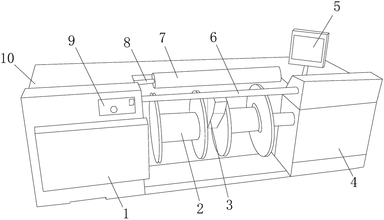
[0023] see Figure 1-Figure 4, the present invention provides a robot unwinding device: its structure includes a cabinet door 1, a machine head 2, a fixed groove 3, a friction deceleration device 4, a controller 5, a fixed rod 6, a bobbin 7, a rotating bearing 8, a mode Adjustment button 9, winding equipment body 10, the cabinet door 1 is fixed on the left side of the surface of the winding equipment body 10 by screws, the machine head 2 is fixed on the left side of the friction deceleration device 4 by a screw, and the friction deceleration The device 4 is welded on the right side of the surface of the winding device body 10, the fixing groove 3 is fixed between the two machine heads 2 by screws, the fixing rod 6 is fixed on the left side of the ...


PUM


Abstract

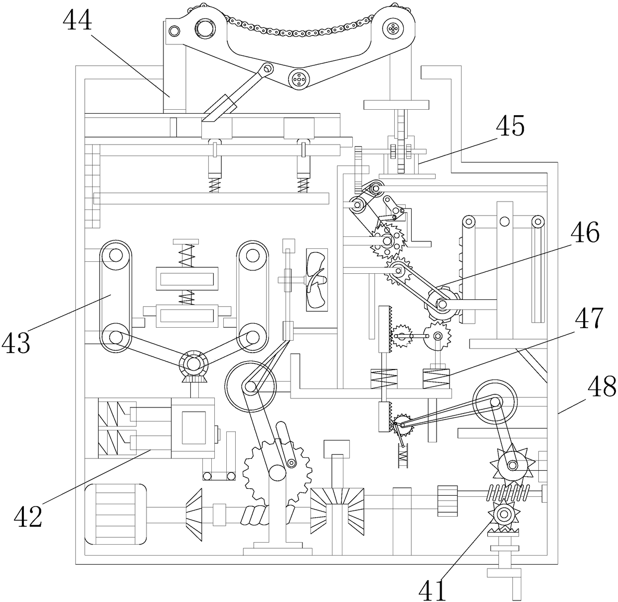
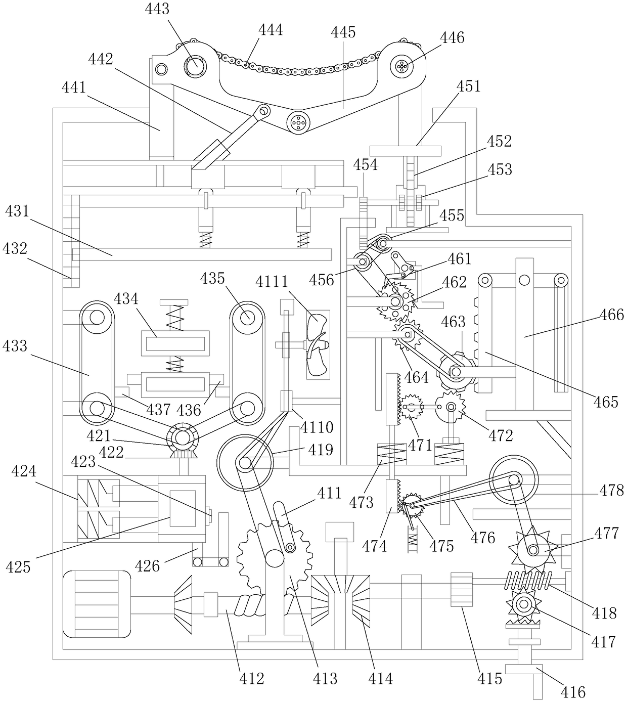
The invention discloses a robot unwinding device which structurally comprises a cabinet door, machine heads, a fixing groove, a frictional speed reducing device, a controller, a fixing rod, a windingpipe, a rotary bearing, a mode adjusting button and a winding device body. The frictional speed reducing device is provided with a start work device, a motor driving device, a pulley moving device, aspeed-reducing connection device, an ejection device, a transmission device, an adjusting rise device and a metal frame. The robot unwinding device has the advantages that due to the fact that the frictional speed reducing device is added in the device, wires wound around an unwinding machine of the device can be stable in unwinding tension, an internally arranged connecting friction chain can bebuckled with rotary gears in the machine heads, the inertia forces produced by the machine heads during rotation are buffered by the chain, the frictional forces corresponding to the inertia forces and between a frictional bearing and a frictional rotary wheel change, accordingly unified adjustment of the rotation speeds of all machine heads is achieved, and reverse winding faults can be avoided.

Description

technical field [0001] The invention relates to a robot unwinding device, which belongs to the field of unwinding devices. Background technique [0002] A robot is a machine device that performs work automatically. It can accept human commands, run pre-programmed programs, and act according to principles formulated with artificial intelligence technology. Its task is to assist or replace human work, such as In the production industry, construction industry, or dangerous work, when the head of a robot unwinding device commonly used in the current technology is rotating, due to inertia, when the rotation speed of the head is faster than the pulling speed of the pull wire, Or with the continuous reduction of the winding wire, when the rotation speed of the machine head is accelerated, the winding wire will be reversely wound, so that the wire is wound on the bobbin, and sometimes it will be knotted and cause the wire to break, which will affect the normal work and cause The wo...

Claims


Application Information

Patent Timeline
IPC IPC(8): B65H59/04
CPCB65H59/04
Inventor 陈明秋
Owner 国电内蒙古东胜热电有限公司
Learn More