Induction type three-phase asynchronous torque motor unwinding driving circuit and method

A torque motor and three-phase asynchronous technology, which is applied in the field of induction three-phase asynchronous torque motor unwinding drive circuit, can solve the problem of requiring dozens of torque motors at least, and one or two hundred at most, wasting labor and time, and implementing Cost increase and other issues, to save manpower and time costs, reduce the effect of control costs

Active Publication Date: 2019-01-18
NEWTRY COMPOSITE
11 Cites 0 Cited by

AI-Extracted Technical Summary

Problems solved by technology

At present, domestic torque motors generally use torque controllers. This kind of controller needs to adjust the voltage on site and control the output torque to maintain the constant tension of the yarn. This is only suitable for a single motor to cont...

Method used

Inductive three-phase asynchronous torque motor unwinding driving circuit among the present invention has reduced motor control cost, has saved the manpower and time cost that manual debugging brings, in use, only need first obtain by a large amount of experimental data The corresponding data table and graph of trigger angle and torque are stored in the main control circuit, and when the corresponding trigger angle is output, the torque motor can be driven to output the current required torque value. Specifically, the tension value F required by the yarn is set by ...

Abstract

The invention relates to the technical field of motors, in particular to an induction type three-phase asynchronous torque motor unwinding driving circuit. The circuit comprises a power supply circuit, a synchronizing signal pulse trigger circuit, a main control circuit and three trigger angle control circuits, wherein the power supply circuit is used for rectification and voltage reduction of three-phase electricity AC380 and power supply; the synchronizing signal pulse trigger circuit as an analog differential comparator circuit comprises two comparators, and the reference voltages of the two comparators are used for being separately compared with the voltage of an AC 220 unidirectional alternating-current sine wave power supply, so that a zero pulse signal is formed; the main control circuit is used for obtaining a required trigger angle signal with the zero pulse signal as a reference signal; the three trigger angle control circuits correspond to three synchronizing signal triggercircuits respectively, and when the three trigger angle control circuits are triggered at the same time, a torque motor outputs torque. Output of the motor torque is quickly achieved at low cost, so that control over constant tension of yarn is achieved. The invention further provides an induction type three-phase asynchronous torque motor unwinding driving method.

Application Domain

Technology Topic

Image

  • Induction type three-phase asynchronous torque motor unwinding driving circuit and method

Examples

  • Experimental program(1)

Example Embodiment

[0030] The specific embodiments of the present invention will be described in further detail below in conjunction with the drawings and embodiments. The following examples are used to illustrate the present invention, but not to limit the scope of the present invention.
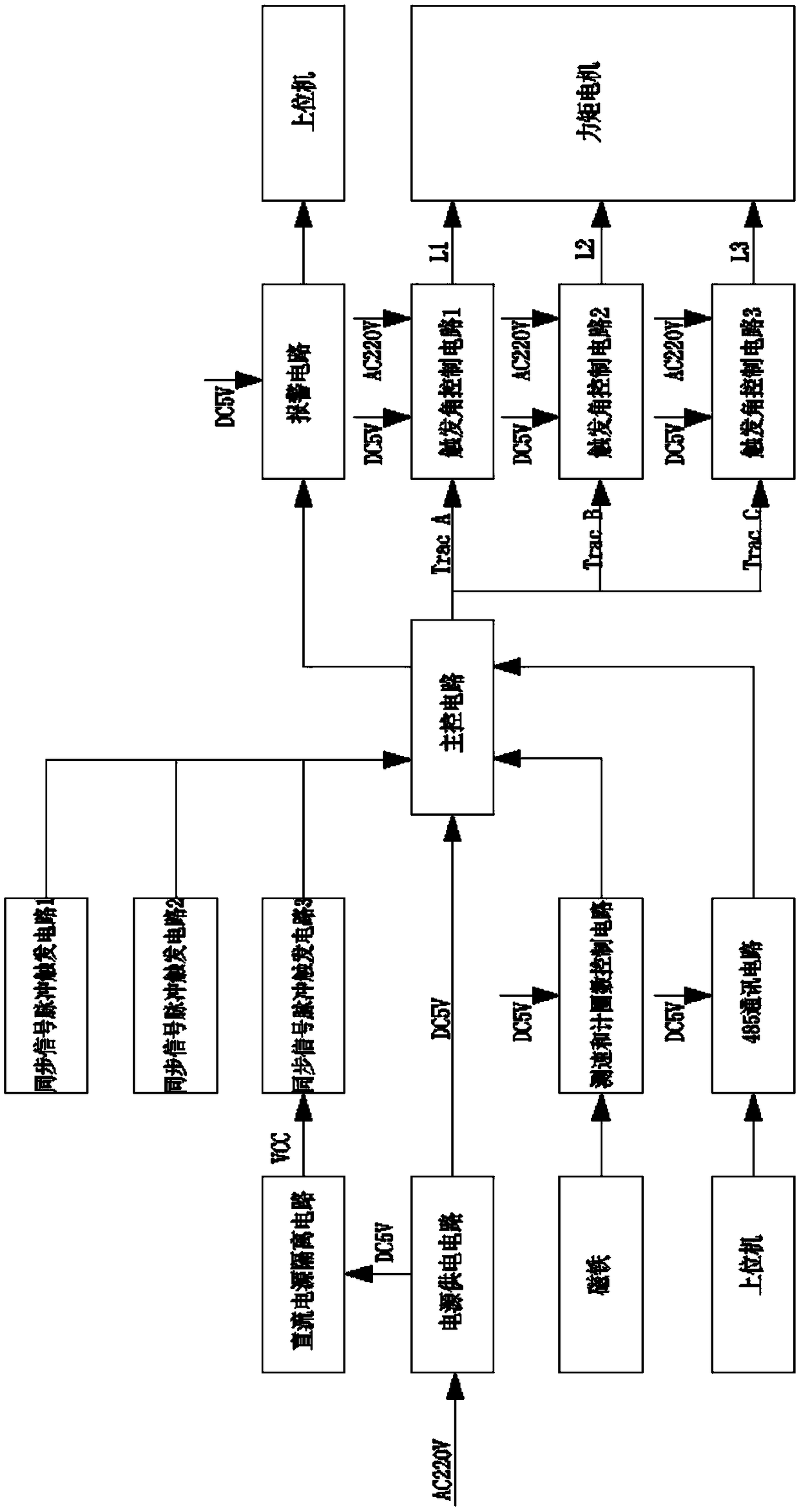
[0031] The inductive three-phase asynchronous torque motor unwinding drive circuit in the present invention includes: a power supply circuit, a synchronous signal pulse trigger circuit, a main control circuit, and a trigger angle control circuit; wherein the power supply circuit is used to perform three-phase power AC380 Rectification and step-down are DC5V, and respectively supply power to the synchronous signal pulse trigger circuit, the main control circuit and the firing angle control circuit; the synchronous signal pulse trigger circuit is an analog differential comparator circuit, which includes two comparators and two comparators. The reference voltage is used to compare the voltage with the AC220 unidirectional AC sine wave power supply, and form a zero-crossing pulse signal; the main control circuit uses the zero-crossing pulse signal as the reference signal, and obtains the required trigger angle signal through calculation and delay. The trigger angle control circuit is turned on; the three trigger angle control circuits correspond to the three synchronization signal trigger circuits. When the three trigger angle control circuits are triggered together, the torque motor outputs torque; the specific implementation process also needs to include speed measurement and metering Turn control circuit, alarm circuit, and 485 communication circuit. Among them, the speed measurement and turn count control circuit receives the tension value parameter of the set motor sent from the host computer. The speed measurement and turn count control circuit is a magnetic rotary encoder, which passes A Phase or B phase can count the number of pulses and count the number of Z-phase turns. When the circuit is abnormal, the alarm circuit can cut off the power supply and give an alarm for timely and effective treatment and warning of the problem.
[0032] The inductive three-phase asynchronous torque motor unwinding drive circuit in the present invention reduces the cost of motor control and saves the labor and time costs caused by manual debugging. During use, only a large amount of experimental data is required to obtain the trigger angle and The corresponding data table and graph of the torque are stored in the main control circuit, and the torque motor can be driven when the corresponding trigger angle is output, and the current required torque value is output. Specifically, the upper computer sets the tension value F required by the yarn, and the 485 communication circuit transmits it to the main control circuit. D can be measured and calculated by the measuring device, so that the current required tension value M can be obtained. The main control circuit is based on The trigger angle and torque corresponding data table stored in advance, output the corresponding trigger angle, control the trigger angle control circuit to drive the torque motor, and output the current torque value, that is, the current yarn tension value can be maintained through the unwinding device.
[0033] As a preference of the above-mentioned embodiment, it also includes a DC power isolation circuit, which is used to separately supply power to the synchronous signal pulse trigger circuit. Therefore, this circuit is an analog differential comparison circuit and needs to prevent interference to ensure control accuracy.
[0034] An induction type three-phase asynchronous torque motor unwinding driving method includes the following steps:
[0035] Step 1: According to the required tension value of the yarn, determine the required motor torque under any winding diameter by the formula M=FD, where D is the real-time winding diameter, F is the yarn tension, and M is the motor torque;
[0036] Step 2: Adjust the motor torque to the required value in step 1 by adjusting the trigger angle of the motor's power supply voltage. In order to avoid interference with the differential comparison circuit, the motor's sine wave trigger circuit is independently powered. .
[0037] Among them, in step 1, the formula for calculating the winding diameter is as follows:
[0038] D=2W/πgN
[0039] D is the real-time winding diameter;
[0040] W is the weight of the wound yarn;
[0041] g is the yarn weight in meters;
[0042] N is the current number of winding turns.
[0043] In the specific implementation process, in step two, adjusting the trigger angle of the motor power supply voltage includes the following steps: use AC220 single-phase AC sine wave power input to step down and compare with the reference voltages of the two comparators in the differential comparison circuit to obtain The sine wave is larger than the two rectangular pulses respectively output by the positive terminal of the first comparator and the negative terminal of the second comparator. The two rectangular pulses are superimposed, and the time of the common trigger is the zero-crossing pulse time, which is obtained every half cycle A zero-crossing point trigger signal. The zero-crossing point trigger signal is input to the main control circuit at a high level. The main control circuit uses the zero-crossing point signal as a reference signal to obtain the required trigger angle signal to adjust the trigger angle of the motor power supply voltage. Yes, through the synchronization signal pulse trigger circuit, three zero point trigger pulses with a phase difference of 120° can be obtained, namely AC sine waves, and one pulse is output at the zero crossing; through this zero point trigger signal, the main control circuit calculates and delays the time, Get the desired trigger angle, when the three trigger angle control circuits are triggered together, the torque motor outputs torque.
[0044] The above are only the preferred embodiments of the present invention, and are not intended to limit the present invention. It should be pointed out that for those of ordinary skill in the art, several improvements can be made without departing from the technical principles of the present invention. And modifications, these improvements and modifications should also be regarded as the protection scope of the present invention.

PUM

no PUM

Description & Claims & Application Information

We can also present the details of the Description, Claims and Application information to help users get a comprehensive understanding of the technical details of the patent, such as background art, summary of invention, brief description of drawings, description of embodiments, and other original content. On the other hand, users can also determine the specific scope of protection of the technology through the list of claims; as well as understand the changes in the life cycle of the technology with the presentation of the patent timeline. Login to view more.

Similar technology patents

Classification and recommendation of technical efficacy words

  • Lower control costs
  • Save manpower and time cost
Why Eureka
Try Eureka