Adjustable axial-torsion coupling vibration suppression device for drill string

A technology of coupling vibration and suppression devices, which is applied in the direction of drill pipes, drill pipes, drilling equipment, etc., can solve the problems of poor torsional vibration suppression effect, difficulty in ensuring strength, and high cost, so as to ensure energy consumption, improve production efficiency, and improve Effect of Vibration Suppression

Active Publication Date: 2019-01-18
NORTHEASTERN UNIV
View PDF8 Cites 1 Cited by
  • Summary
  • Abstract
  • Description
  • Claims
  • Application Information

AI Technical Summary

Problems solved by technology

[0004] For the drill string vibration suppressing device in the prior art, there are generally following deficiencies: 1. It is necessary to redesign the drill string drill bit connection device, which is costly and difficult to guarantee the strength; 2. The spring stiffness, damping and quality of the existing vibration damping device are not It cannot be adjusted, resulting in poor vibration damping effect, and even causing resonance to aggravate the vibration of the drill string; 3. The existing vibration damping devices only suppress the axial vibration of the drill bit or convert torsional vibration into axial vibration and then suppress it. The vibration suppression effect is poor; 4. The active drill bit vibration suppression device needs to install sensors, solenoid valves, and cables, and the reliability is poor in the face of harsh deep well environments; 5. The drill bit of the passive drill bit vibration suppression device will be compressed when it is cut. The disc spring thus causes the piston to move prematurely in the cylinder, making the unit less sensitive to vibrations

Method used


Image

  • Adjustable axial-torsion coupling vibration suppression device for drill string
  • Adjustable axial-torsion coupling vibration suppression device for drill string
  • Adjustable axial-torsion coupling vibration suppression device for drill string

Examples


Embodiment Construction

[0039] The present invention will be further described in detail below in conjunction with the accompanying drawings, so that those skilled in the art can implement it with reference to the description.

[0040] As shown in the figure, the present invention provides an adjustable drill string axial-torsional coupling vibration suppression device, and the technical scheme is as follows:

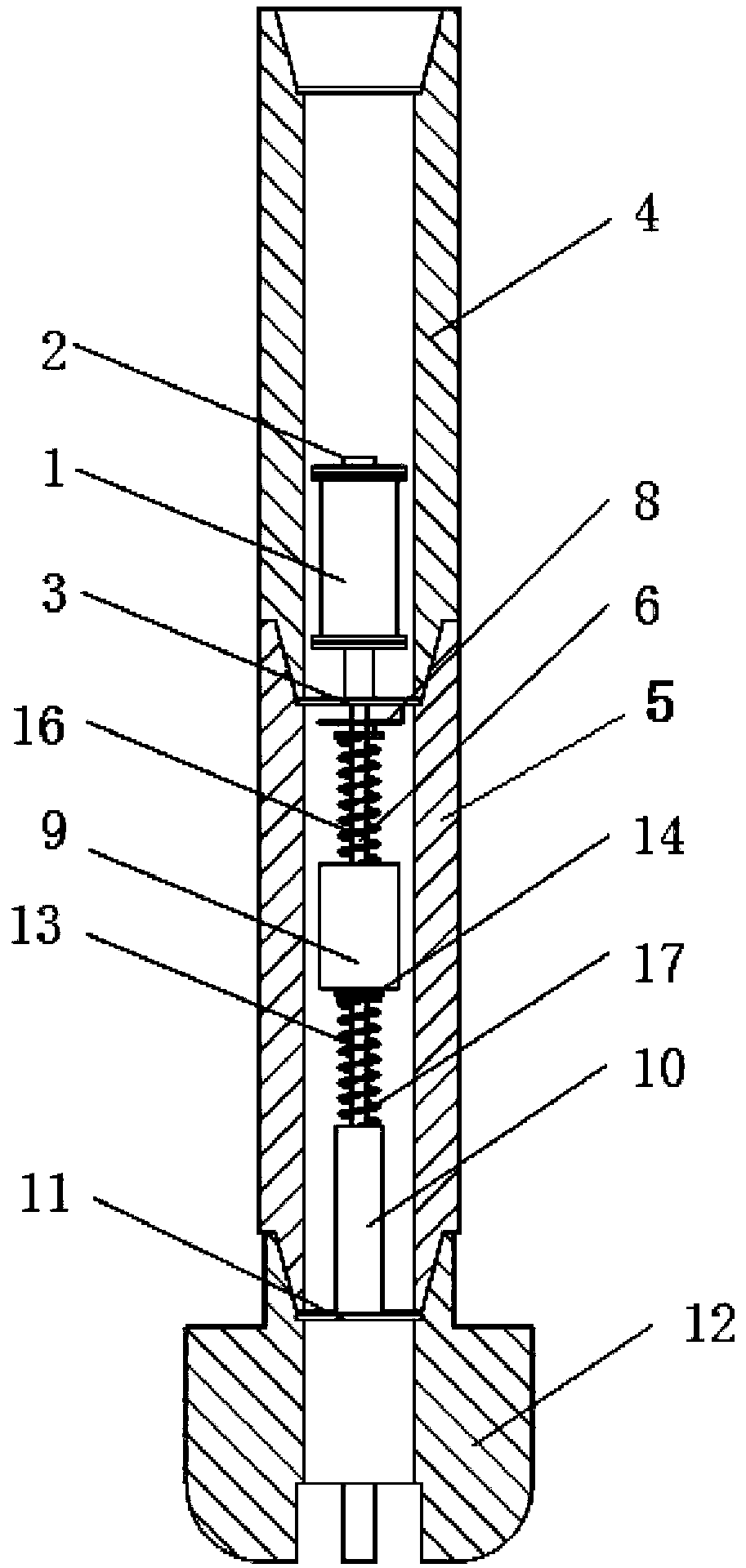
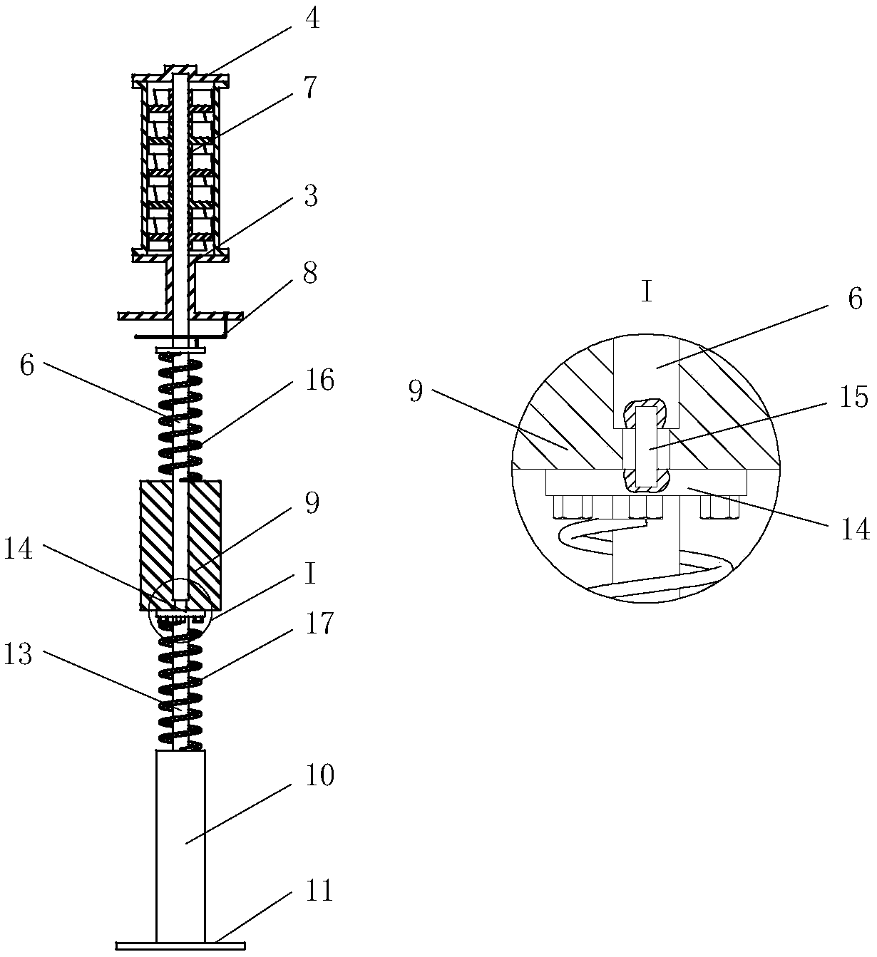
[0041] The rotary damping cylinder 1 is a cylindrical hollow structure, the upper part of the rotary damping cylinder 1 is connected with the shaft sealing cover 2; the lower part of the rotary damping cylinder 1 is connected with the through-flow transparent cover 3; The connection between the drill collar 4 and the lower drill collar 5; a rotating shaft 6 is installed in the middle of the rotating damping cylinder 1, and a rotating blade 7 is installed on the upper part of the rotating shaft 6; a rotating elastic element 8 is installed above the middle part of the rotating shaft 6, so that T...


PUM


Abstract

The invention discloses an adjustable axial-torsion coupling vibration suppression device for a drill string. A rotary damping structure and an axial damping structure are arranged in a drill collar.In the working process, a mass block absorbs the energy generated by the vibration of the drill string, the energy generated by the torsional vibration is consumed by a rotary elastic element and a rotary damping cylinder, and the energy generated by the axial vibration is consumed by an axial spring and an axial damping cylinder. The assembly of the whole transposition is through the match and the clamping of a boss and a groove, which is of high installation efficiency. The damping, stiffness and mass of the adjustable axial-torsion coupling vibration suppression device for a drill string can be adjusted. The adjustable axial-torsion coupling vibration suppression device is arranged inside the drill collar. The scour of the drilling fluid is beneficial to the cooling of the suppression device, so that the working performance of the system is ensured. A plurality of adjustable axial-torsion coupling vibration suppression device can be arranged in a plurality of drill collars to suppress the vibration of the entire drill string.

Description

technical field [0001] The invention relates to the technical field of drilling, in particular to an adjustable drill string axial-torsional coupling vibration suppression device. Background technique [0002] During the drilling process, as the depth of the drill hole increases, the length of the drill string will continue to increase, reaching a length of several thousand meters. At this time, the rigidity of the drill string will be greatly reduced. The column generates self-excited vibrations. The self-excited vibration frequency of the drill string is very close to the natural frequency of the drill string, which can easily lead to the intensification of drill string vibration and instability, and can easily lead to premature fatigue damage of the drill string, and even cause the drill string to break. The self-excited vibration of the drill string is mainly manifested as axial vibration along the length of the drill string and torsional vibration along the rotational ...

Claims


Application Information

Patent Timeline
Patent Type & Authority Applications(China)
IPC IPC(8): E21B17/07
CPCE21B17/073
Inventor 邓鹏飞李鹤付柯
Owner NORTHEASTERN UNIV
Why Eureka
Try Eureka