
Rotary cylinder device

A rotary and cylinder technology, applied in multi-cylinder pumps, variable capacity engines, liquid variable capacity machines, etc., can solve the problems of low energy conversion efficiency, reduce energy loss, simplify structure, and improve energy conversion efficiency effect

Active Publication Date: 2012-07-11
K R & D
View PDF7 Cites 1 Cited by
  • Summary
  • Abstract
  • Description
  • Claims
  • Application Information

AI Technical Summary

Problems solved by technology

[0004] In the reciprocating drive mechanism, it is easy to reduce the energy conversion efficiency due to the energy loss caused by the reciprocating motion of the piston unit in the cylinder

Method used


Image

  • Rotary cylinder device
  • Rotary cylinder device
  • Rotary cylinder device

Examples


Embodiment Construction

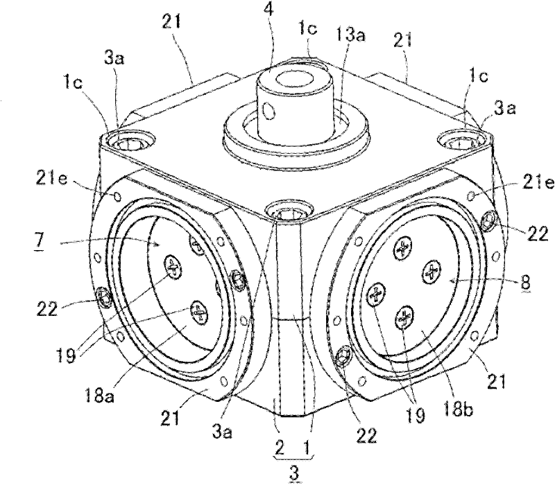
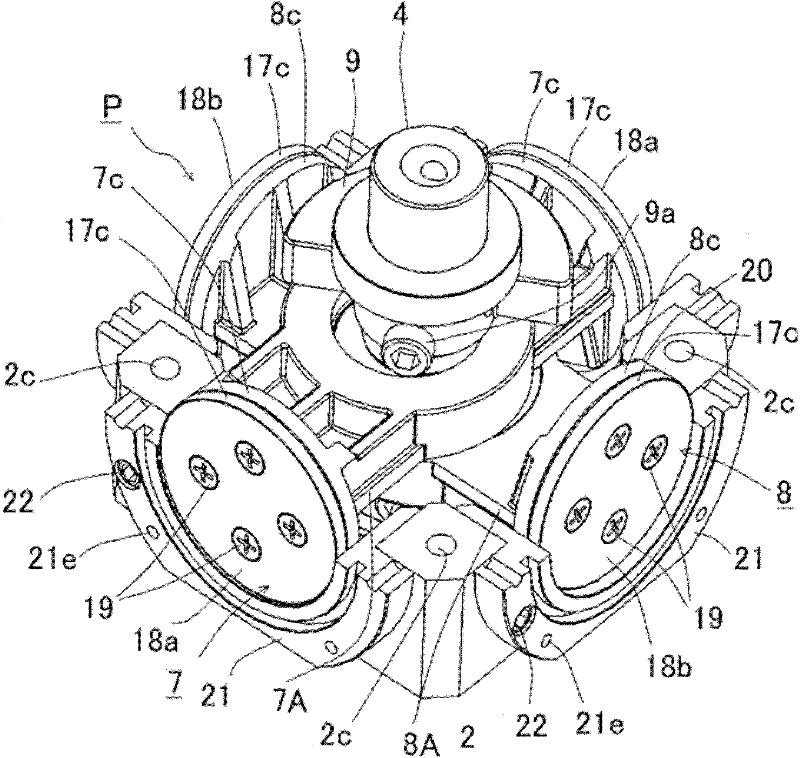
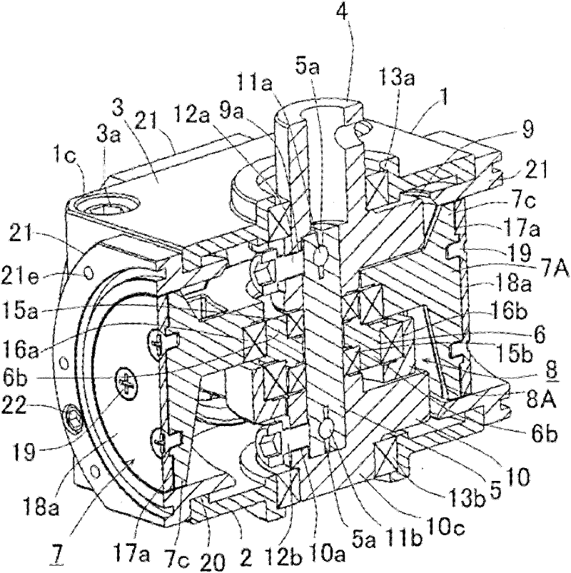
[0069] Now, preferred embodiments of the present invention will be described in detail with reference to the accompanying drawings. will refer to Figures 1 to 23B A rotary cylinder device to be incorporated in a compressor will be described as an embodiment of the present invention. The rotary cylinder device can convert the reciprocating motion of the piston in the cylinder and the rotary motion of the shaft to each other.

[0070] exist figure 1 Among them, a shaft (input / output shaft) 4 is rotatably held in a main body case 3 composed of a first case 1 and a second case 2 . The first housing 1 and the second housing 2 are integrated by bolts 3 a respectively provided at four corners of the main body housing 3 . Such as image 3 As shown, in the main body housing 3, the eccentric cylindrical body 6 that can rotate around the first crankshaft 5 and constitutes the composite piston assembly P (see figure 2 ) and the first piston unit 7 and the second piston unit 8, whi...


PUM


Abstract

Disclosed is a compact rotary cylinder device wherein rotating parts which are capable of rotating at a uniform speed around a shaft are compactly mounted in both the axial direction and the radial direction of the device, and the rotary motion of the rotating parts around a plurality of crank shafts is combined so as to enable the linear reciprocating motion of a piston group, and noise reduction is achieved by suppressing rotation-induced vibrations by achieving mass balance of the rotating parts. First, second and third rotational balances are balanced by means of first and second balance weights (9, 10). The first rotational balance is of first and second piston groups (7, 8), centred around second virtual crank shafts (14a, 14b); the second rotational balance is of a piston complex (P), centred around a first crank shaft (5); and the third rotational balance is of the first crank shaft (5) and the piston complex (P), centred around a shaft (4). Whilst in the described balanced state, the first crank shaft (5) rotates around the shaft (4), and the piston complex (P) rotates around the first crank shaft (5), thus the first and second piston groups (7, 8) which are mounted in a second cylinder (6b) move in a linear reciprocating manner along the radial direction of the rolling circle (23) of the second virtual crank shafts (14a, 14b), the rolling circle being centred on the shaft (4) and having a radius of 2r.

Description

technical field [0001] The present invention relates to a rotary cylinder device capable of mutually converting the reciprocating motion of the piston in the cylinder and the rotary motion of the shaft, and more particularly to a rotary cylinder that can be applied to internal combustion engines, compressors, vacuum pumps, hydraulic rotary machines, etc. device. Background technique [0002] In each of the internal combustion engine, compressor, vacuum pump, hydraulic rotary machine, etc., a different type of drive mechanism is employed. For example, a reciprocating drive mechanism that repeatedly sucks in and discharges fluid by the reciprocating motion of a piston unit connected to a crankshaft, a drive mechanism that repeatedly sucks in and discharges fluid by rotating a movable scroll relative to a fixed scroll, etc. A scroll type drive mechanism, a rotary drive mechanism that repeatedly sucks and discharges fluid through the rotational motion of a drum (see JP-A-2004-1...

Claims


Application Information

Patent Timeline
Patent Type & Authority Applications(China)
IPC IPC(8): F01B1/06F01B9/02
CPCF01B1/062F04B35/01F04B1/053F04B27/053F04B9/045F01B1/06F01B9/02
Inventor 小松文人
Owner K R & D
Learn More