Filling apparatus

A technology of filling device and filling port, which is applied in the direction of power device, container filling method, container structure installation device, etc. It can solve the problem of detachment of filling nozzle 30, achieve the effect of reducing sealing structure and improving durability

Active Publication Date: 2019-01-18
TOKYO TATSUNO CO LTD
View PDF6 Cites 0 Cited by
  • Summary
  • Abstract
  • Description
  • Claims
  • Application Information

AI Technical Summary

Problems solved by technology

[0004] But when Figure 7 In the prior art shown, if the rod 35 is not moved toward the direction close to the socket 40 when the pipe joint 31 of the nozzle 30 is connected to the socket 40 serving as the filling port on the vehicle side, the rod 35 is not located in the clutch 34. If the protrusion 34A at the tip is radially outward, the protrusion 34A of the clutch 34 may disengage from the fitting groove 40B, causing the filling nozzle 30 to disengage from the insertion hole 40.

Method used


Image

  • Filling apparatus
  • Filling apparatus
  • Filling apparatus

Examples


Embodiment Construction

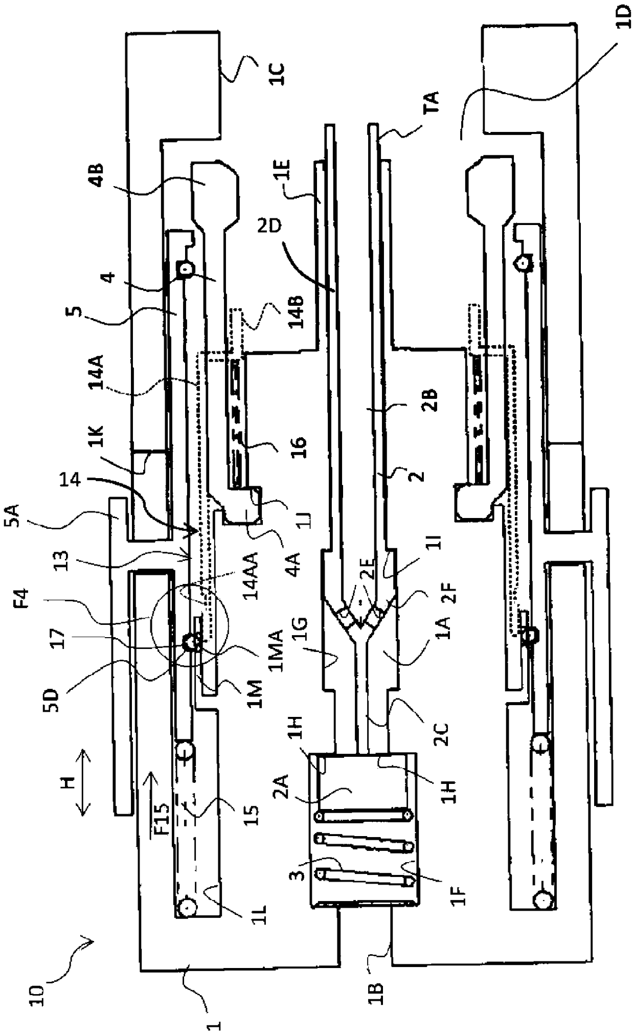
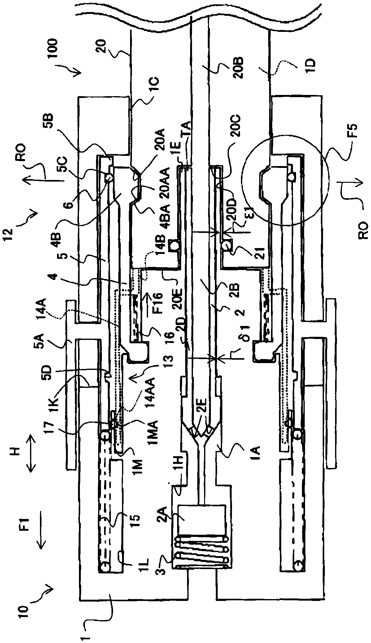
[0058] Below, refer to Figure 1 to Figure 5 Embodiments of the present invention will be described. figure 1 Filling nozzle 10 shown from Image 6 The shown hydrogen fuel storage container 50 fills the vehicle-mounted hydrogen filling container 41 with hydrogen via a fuel filling system (dispenser 60 , filling hose 45 , etc.). The filling nozzle 10 has a pipe joint main body 1 on the hydrogen supply source side of the pipe joint main body 1 (in figure 1 Middle is the left side) the central part of the end (in the figure 1 The center part in the vertical direction) is provided with a hydrogen introduction port 1B connected to the filling hose side (not shown). And, on the side of the socket of the pipe joint main body 1 (the side of the filling port on the vehicle side, on the figure 1 The middle is the right side) end is provided with for jack 20 ( figure 2 ) into opening 1C. On the hydrogen supply source side of the opening 1C in the pipe joint 1 (in figure 1 In ...


PUM


Abstract

To provide a filling apparatus in which when a pipe joint of a filling nozzle and a vehicle side filling port (receptacle) are connected with each other, a lever surely positions outward a swelling portion at an end of a clutch and a condition that the selling portion at the end of the clutch engages an engaging recessed portion of the receptacle is maintained, which allows a condition that the pipe joint of the filling nozzle and the vehicle side filling port (receptacle) are connected with each other to be continued. The filling apparatus (100) including: a storage tank (50); a filling nozzle (10) for filling hydrogen from the storage tank (50) via a fuel filling mechanism and a vehicle side filling port (20) to an in-vehicle hydrogen filling tank (41); a clutch mechanism (12) for maintaining a condition that the filling nozzle (10) and the vehicle side filling port (20) are connected with each other; and a lever position moving mechanism (13) for moving the lever (5) radially outward an end portion of the clutch mechanism (2) on the vehicle side filling port (20) side when the filling nozzle (10) and the vehicle side filling port (20) are connected with each other.

Description

technical field [0001] The present invention relates to a filling device for filling gas such as hydrogen used as fuel, for example. Background technique [0002] For example, regarding vehicles running on hydrogen as fuel, such as Image 6 As shown, at a hydrogen filling place equipped with a hydrogen storage container 50 and a fuel filling system (dispenser 60, filling hose 45, etc.), the filling nozzle 30 is connected to a receptacle (receptacle, socket) 40 serving as a filling port on the vehicle side. Hydrogen gas is filled, and this filling is performed while controlling according to the maximum operating pressure of the hydrogen tank 41 mounted on the vehicle A. In addition, reference numeral 51 denotes a piping system for supplying hydrogen from the hydrogen storage container 50 to the distributor 60 . Regarding such a hydrogen filling device, the present applicant has already proposed a technical proposal (for example, refer to Patent Document 1). This hydrogen fi...

Claims


Application Information

Patent Timeline
Patent Type & Authority Applications(China)
IPC IPC(8): F17C5/06F17C13/00
CPCF17C5/06F17C13/002F17C2223/0123F17C2221/012F17C2270/0168F17C2201/056F17C2205/037F17C2205/0376F17C2225/0123F17C2225/036F17C2260/028F17C5/00F17C2265/065F17C2270/0139F17C2270/0178Y02E60/32F17C13/04F16L37/098F16L37/38B60K15/00B60S5/02B60K15/03006B60K2015/03019B60K2015/03315F17C2205/0329F17C2205/0352F17C2205/0382F17C2250/0636
Inventor 竹泽正浩寺杣友贵木村洁
Owner TOKYO TATSUNO CO LTD
Why Eureka
Try Eureka