
Demodulation system and method of fiber grating sensor based on edge filtering and time division multiplexing

A technology of fiber grating and edge filtering, which is applied in the direction of transmitting sensing components, converting sensor output, and instruments with optical devices, can solve the problems of small sensor capacity, low demodulation frequency, and complex structure of tunable wavelength light source method, and achieve Effect of increasing demodulation frequency and reducing cost

Active Publication Date: 2019-01-18
SHANDONG UNIV
View PDF6 Cites 10 Cited by
  • Summary
  • Abstract
  • Description
  • Claims
  • Application Information

AI Technical Summary

Problems solved by technology

The single edge filter and tunable filter method have small sensor capacity, and the tunable wavelength light source method has complex structure and high system cost
[0004] At present, the large-capacity fiber grating sensing technology based on wavelength division multiplexing multi-channel and time division multiplexing weak reflection grating has been developed to a certain extent, but there are still technical bottlenecks related to complex system structure, high cost, and low demodulation frequency.

Method used


Image

  • Demodulation system and method of fiber grating sensor based on edge filtering and time division multiplexing
  • Demodulation system and method of fiber grating sensor based on edge filtering and time division multiplexing
  • Demodulation system and method of fiber grating sensor based on edge filtering and time division multiplexing

Examples


Embodiment Construction

[0037] The present invention will be further described below in conjunction with the accompanying drawings and embodiments.

[0038] It should be pointed out that the following detailed description is exemplary and intended to provide further explanation to the present application. Unless defined otherwise, all technical and scientific terms used herein have the same meaning as commonly understood by one of ordinary skill in the art to which this application belongs.

[0039] It should be noted that the terminology used here is only for describing specific implementations, and is not intended to limit the exemplary implementations according to the present application. As used herein, unless the context clearly dictates otherwise, the singular is intended to include the plural, and it should also be understood that when the terms "comprising" and / or "comprising" are used in this specification, they mean There are features, steps, operations, means, components and / or combinatio...


PUM


Abstract

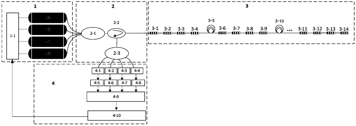
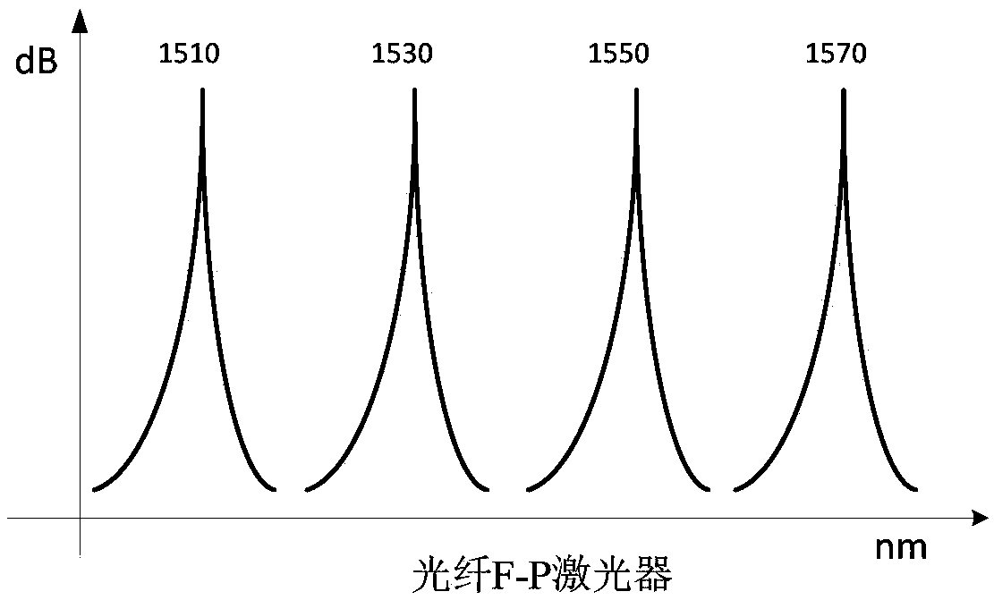
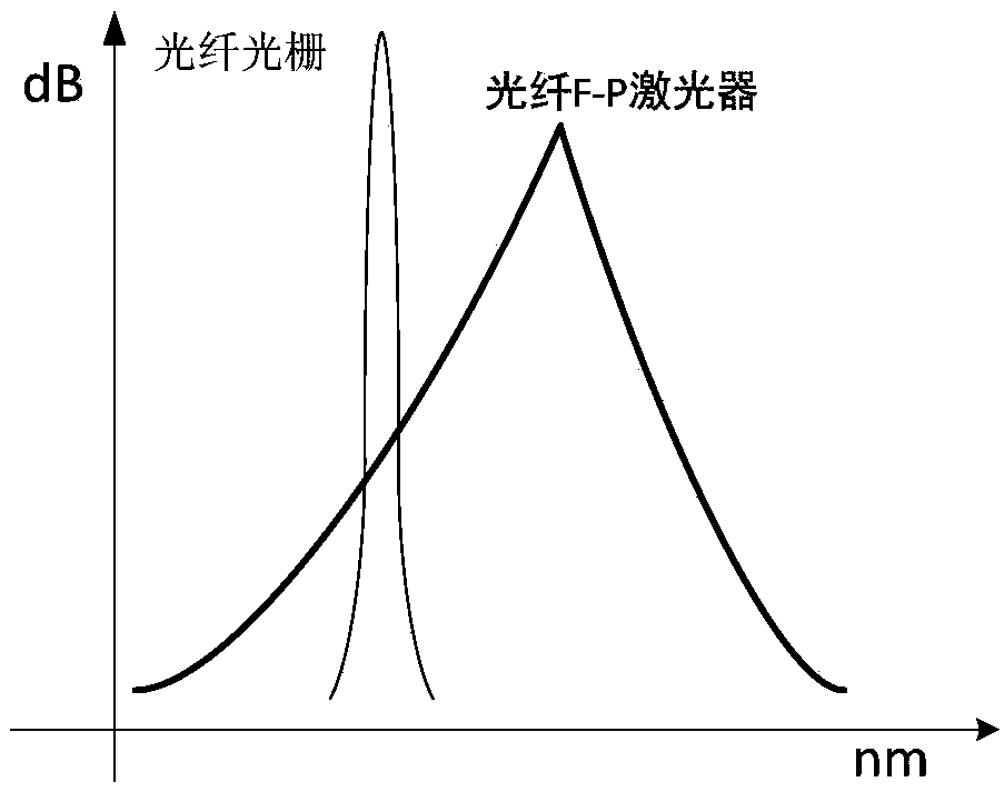
The invention discloses a demodulation system and method of a fiber grating sensor based on edge filtering and time division multiplexing. A plurality of fiber F-P lasers with different center wavelengths transmit laser signals of respective central wavelengths. The laser signals through a fiber into a circulator. The circulator injects a combined laser into a sensing unit. The sensing unit comprises a plurality of sets of sensing arrays connected in series. Each set of sensing arrays comprises a plurality of fiber gratings connected in series corresponding to different center wavelengths. Each of the sensing arrays is connected by a time division delay fiber. The circulator simultaneously receives the optical signal fed back by the sensing unit, and separates the different wavelengths ofthe incident light and transmits the same to a processing unit. The processing unit amplifies the optical signals of different wavelengths and performs edge filtering. The processing unit demodulatesthe fiber grating sensing arrays with the same wavelength type according to the signal return time. High frequency demodulation of a large-capacity fiber grating sensing array on a single fiber can beachieved by combining edge filtering and time division multiplexing.

Description

technical field [0001] The invention relates to an optical fiber grating sensing demodulation system and method based on edge filtering and time division multiplexing. Background technique [0002] Optical fiber sensing technology is a new type of sensing technology that uses light as the carrier and optical fiber as the medium to perceive and transmit external signals (measured) and has developed rapidly with the development of optical fiber and optical fiber communication technology. Fiber Bragg grating is one of the typical optical fiber sensing devices, and its central wavelength has a good linear relationship with temperature and stress applied to the grating. distributed sensing. At present, the development trend of fiber grating sensor technology is as follows: on the one hand, the sensor types of fiber grating sensing system are becoming more and more abundant, the sensing ability is greatly enhanced, and the system scale is continuously expanding; In the direction...

Claims


Application Information

Patent Timeline
IPC IPC(8): G01D5/353
CPCG01D5/35312G01D5/35387G01D5/3539
Inventor 姜明顺张法业张雷隋青美曹玉强贾磊
Owner SHANDONG UNIV
Learn More