Automatic dyeing device and control method thereof

An automatic dyeing and controller technology, applied in the field of biochemical dyeing, can solve the problems of large amount of reagents, small application range, uneven coverage of dye solution, etc., to reduce the phenomenon of uneven dye solution, improve dyeing efficiency and precision, Ease of daily maintenance

Pending Publication Date: 2019-01-18
TIANJIN YUANTIANSHENG TECH DEV
View PDF8 Cites 7 Cited by
  • Summary
  • Abstract
  • Description
  • Claims
  • Application Information

AI Technical Summary

Problems solved by technology

At present, manual dyeing needs to go through steps such as primary dyeing, decolorization, and re-staining. Manual operation is prone to inconsistency, low accuracy, and slow dyeing speed, which wastes a lot of manpower and material resources, and the dyeing efficiency is poor.
[0003] At present, there have been automatic dyeing devices on the market, but the dyeing effect is not good or the amount of reagents is large, and the phenomenon of uneven coverage of the dye solution occurs, and pollution will be generated during the dyeing process, and the dyeing function of the existing dyeing devices Single, complex operation, incompatible with various staining experiments, small scope of application

Method used


Image

  • Automatic dyeing device and control method thereof
  • Automatic dyeing device and control method thereof
  • Automatic dyeing device and control method thereof

Examples


Embodiment 1

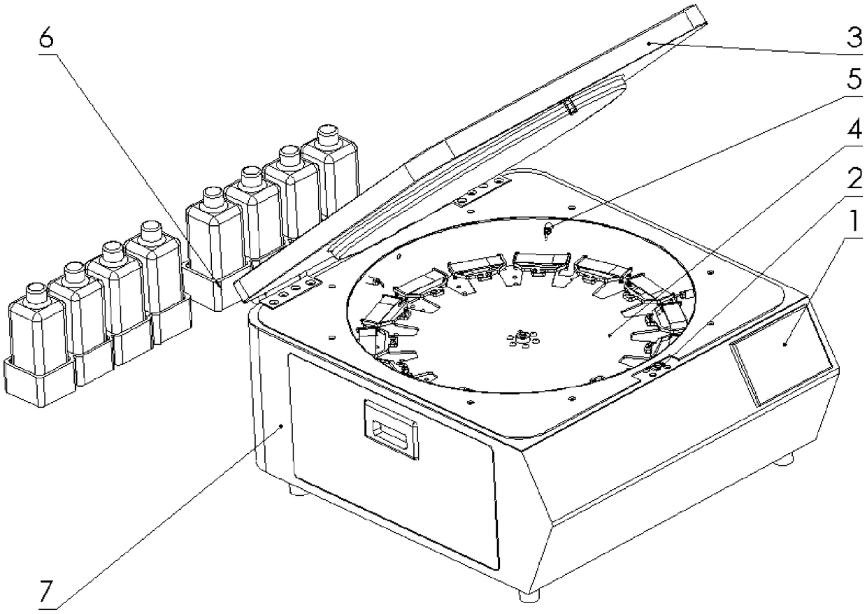
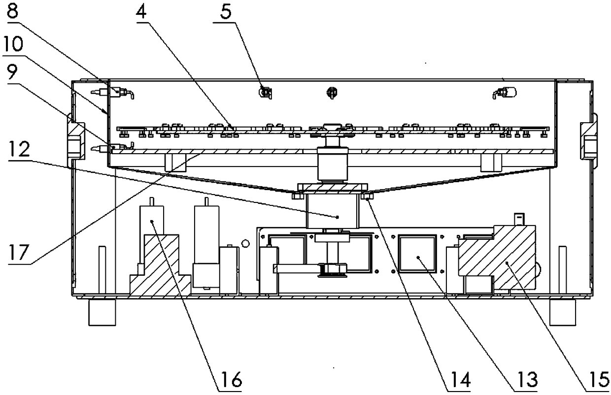
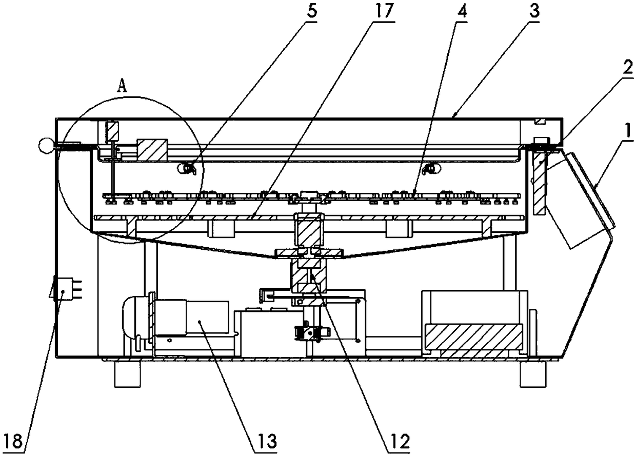
[0050] Such as Figure 1-6 As shown, the automatic dyeing device of the present invention includes a housing 7, a cover 3, a dripping mechanism installed in the housing 7 for dripping and dyeing a sample, a detection mechanism for detecting the position and quantity of the sample, and A cleaning mechanism inside the cleaning device, a rotating mechanism for centrifuging samples, and a reagent detection mechanism for detecting the amount of reagents installed on the outside of the housing 7. The housing 7 is provided with a cover lock 2 and a cover lock 2 Used to lock the position of the cover plate 3 so that the housing 7 forms a closed space; the dripping mechanism includes a plurality of dripping nozzles 5 and a dye peristaltic pump 13, which passes through the dripping pipeline and the dripping nozzle 5 Connection; the detection mechanism includes a sensor support 20, a sensor 19, a protective baffle 23, and a pushing component 22 mounted on the cover 3, the sensor support 2...

Embodiment 2

[0067] On the basis of Embodiment 1, a display screen 1 is installed on the housing 7, and the controller is electrically connected to the display screen 1. The display screen adopts a touch screen to facilitate the user to select an experiment mode.

[0068] When pipeline maintenance is required, take a pipeline connected with a reagent bottle as an example. The dye peristaltic pump 13 is turned over to recover the reagents in the pipeline into the reagent bottle. After the recovery is completed, the dye peristaltic pump 13 is stopped and then turned on The solenoid valve communicated with the cleaning water pump 16, the cleaning liquid enters the dyeing liquid pipeline to flush the pipeline.

[0069] A liquid level sensor is inserted in the reagent bottle to monitor the remaining amount of the reagent in the reagent bottle, and is electrically connected to the controller and the display screen 1 to remind the user to replace the reagent in time.

Embodiment 3

[0071] On the basis of embodiment 1, a heating assembly is also provided in the housing 7 for heating the interior of the housing 7. The heating assembly includes a heater and a temperature sensor, and the heater and the temperature sensor are electrically connected to the controller. When the reagent needs Jarvan, start the heater to heat the reagent in the pipeline. After the temperature sensor detects that the reagent is heated to a preset threshold temperature, the dye solution peristaltic pump 13 is started to work, and the reagent is sprayed from the drip nozzle 5.

[0072] Furthermore, the controller can be programmed to preset a variety of experiments, and the reagent types and experimental requirements can be modified according to the needs of users.

[0073] The device can increase or decrease the number of the dripping nozzle 5, the dye peristaltic pump 13 and other components according to the experimental requirements, and the types of reagents are not limited.


PUM


Abstract

The invention discloses an automatic dyeing device. The device comprises: a shell body; a cover plate; a dripping dyeing mechanism, which is installed in the shell body, and is used for dyeing on samples; a detecting mechanism, which is used for detecting positions and the number of the samples; a cleaning mechanism, which is used for cleaning the inside of the device; a rotating mechanism, whichis used for centrifuging on the samples; and a reagent detecting mechanism, which is installed outside the shell body, and is used for detecting the use amount of a reagent. The detecting mechanism includes a sensor support seat installed on the cover plate, a sensor, a protection baffle and a pushing component. The sensor support seat is installed on the cover plate. The sensor is installed on the sensor support seat. A light transmission hole corresponding to a position of the sensor is disposed on the cover plate. The protection baffle is disposed on the light transmission hole. The devicehas the advantages that positions and the number of glass slides are detected through the sensor, positions where dyeing liquid droplets fall on the glass slides are effectively controlled, waste of the reagent is reduced, the light transmission hole is completely blocked through the protection baffle after detection completion, and a case where the reagent in experiment contaminates the sensor, and thus impacts accuracy of detecting is avoided.

Description

Technical field [0001] The invention belongs to the field of biochemical dyeing, and in particular relates to an automatic dyeing device. Background technique [0002] Artificial staining or instrumental staining is usually used in the fields of hematology staining, microbial staining, pathological staining, cytology staining, and reproductive staining. At present, manual dyeing needs to go through the steps of primary dyeing, decoloring, and counter-dyeing. Manual operation is prone to inconsistency, low accuracy, and slow dyeing speed, which wastes a lot of manpower and material resources, and dyeing efficiency is poor. [0003] At present, automatic dyeing devices have appeared on the market, and their dyeing effect is not good or the amount of reagents is large, and the phenomenon of uneven coverage of the dye solution occurs, pollution will occur during the dyeing process, and the dyeing function of the existing dyeing device Single, complicated operation, incompatible with m...

Claims


Application Information

Patent Timeline
Patent Type & Authority Applications(China)
IPC IPC(8): G01N1/31
CPCG01N1/31
Inventor 董维来陈亮杨智力
Owner TIANJIN YUANTIANSHENG TECH DEV
Why Eureka
Try Eureka