Nuclear power plant passive reactor cavity water injection system

A reactor cavity water injection and passive technology, applied in the field of nuclear power, can solve the problems of increasing equipment maintenance, operation and maintenance, increasing the capacity of water injection tank, and large flow change range, so as to improve economy and layout feasibility, reduce layout difficulty, The effect of small fluctuation range

Pending Publication Date: 2019-01-18
中广核工程有限公司 +2
View PDF5 Cites 6 Cited by
  • Summary
  • Abstract
  • Description
  • Claims
  • Application Information

AI Technical Summary

Problems solved by technology

[0007] 2) There is a certain deviation in the set pressure behind the pressure reducing valve, which causes the top pressure of the water injection tank to be in a pressure range, and the water injection flow rate of the system may exceed the design flow range of the system;
[0008] 3) The orifice plate is used to control the water injection flow, which requires high design pressure of pressure storage containers, water injection tanks, valves and other equipment and connected pipelines, which is poor in economy and increases the risks of equipment maintenance and operation maintenance;
[0009] 4) The orifice plate is used to control the water injection flow, and the flow range is too large, which causes a certain waste of water source and increases the capacity of the water injection tank

Method used


Image

  • Nuclear power plant passive reactor cavity water injection system
  • Nuclear power plant passive reactor cavity water injection system

Examples


Embodiment Construction

[0038] In order to make the purpose, technical solution and technical effect of the present invention clearer, the present invention will be further described in detail below in conjunction with the accompanying drawings and specific embodiments. It should be understood that the specific implementations described in this specification are only for explaining the present invention, not for limiting the present invention.

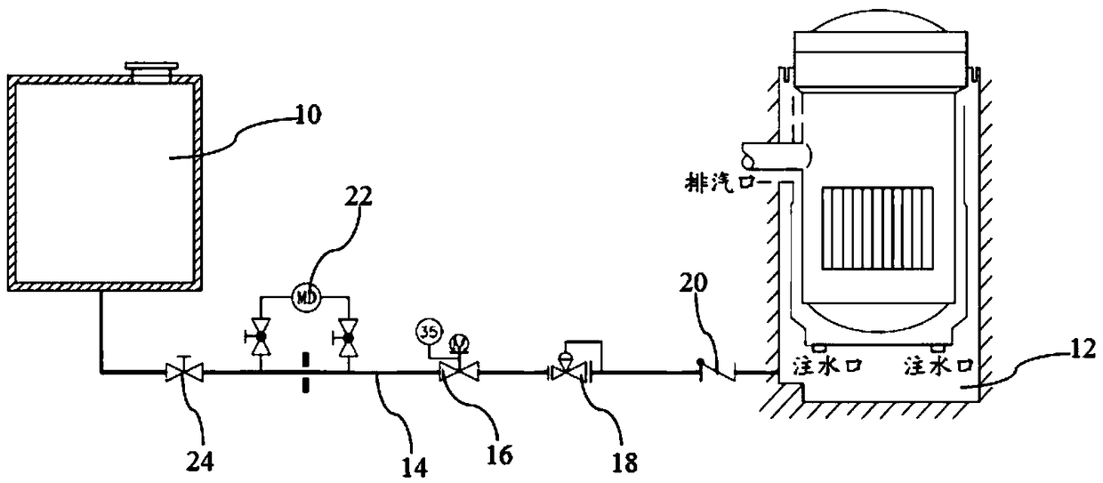
[0039] see figure 1 As shown, the nuclear power plant passive reactor cavity water injection system of the present invention includes:

[0040] The water injection tank 10 is used for storing water and injecting water into the reactor cavity 12;

[0041] The water injection pipeline 14 is connected to the bottom of the water injection tank 10 at one end and connected to the reactor cavity 12 at the other end, for injecting the water in the water injection tank 10 into the reactor cavity 12;

[0042] An electric isolation valve 16, arranged on the water inje...


PUM


Abstract

The invention discloses a nuclear power plant passive reactor cavity water injection system. The nuclear power plant passive reactor cavity water injection system comprises a water injection tank, a water injection pipeline, an electric isolation valve and a self-actuated flow control valve assembly, wherein the water injection tank is used for storing water, and injecting water into a reactor cavity; one end of the water injection pipeline is connected with the bottom of the water injection tank, and the other end is connected with the reactor cavity; the water injection pipeline is used forinjecting water in the water injection tank into the reactor cavity; the electric isolation valve is arranged on the water injection pipeline, and is used for controlling the communication or isolation between the water injection tank and the reactor cavity; the self-actuated flow control valve assembly is arranged on the water injection pipeline between the electric isolation valve and the reactor cavity, takes potential energy of the water in the water injection tank as a power source, and is used for keeping water injection flow of the water injection tank in an approximately-stable state.Compared with the prior art, the nuclear power plant passive reactor cavity water injection system has the advantages of simple structure, convenience in arrangement, stable flow control, low requirement on water injection tank distribution, saving in water resources, and capability of improving the running safety of nuclear power plants.

Description

technical field [0001] The invention belongs to the field of nuclear power, and more specifically, the invention relates to a passive reactor cavity water injection system of a nuclear power plant. Background technique [0002] At present, newly-built nuclear power plants and nuclear power plants in service at home and abroad are equipped with core melt retention systems after severe accidents to alleviate severe accidents and prevent the release of radioactive substances, mainly including two technical solutions: retention inside the pressure vessel and retention outside the pressure vessel . [0003] For stagnation outside the pressure vessel, it mainly provides a passive pressurized water reactor nuclear power plant core catcher with a molten material expansion chamber, which expands, retains and cools the molten material when the pressure vessel fails. After a serious accident, assuming that the pressure vessel is melted through, a core capture, cooling and stabilizatio...

Claims


Application Information

Patent Timeline
Patent Type & Authority Applications(China)
IPC IPC(8): G21C15/18
CPCG21C15/18Y02E30/30
Inventor 高清李振光李盛杰蒋燕祥彭跃胡剑周绍飞吴小天
Owner 中广核工程有限公司
Why Eureka
Try Eureka